
V-process production line

A production line and cable technology, which is applied to the parts of molding machines, casting molding equipment, casting molds, etc., can solve the problems of time-consuming and labor-intensive work efficiency, and achieve the effects of stable transfer and transportation, prevention of lateral deviation, and time-saving and labor-saving work efficiency.

Active Publication Date: 2019-10-08
DINGZHOU DONGFANG FOUNDRY
View PDF9 Cites 1 Cited by
  • Summary
  • Abstract
  • Description
  • Claims
  • Application Information

AI Technical Summary

Problems solved by technology

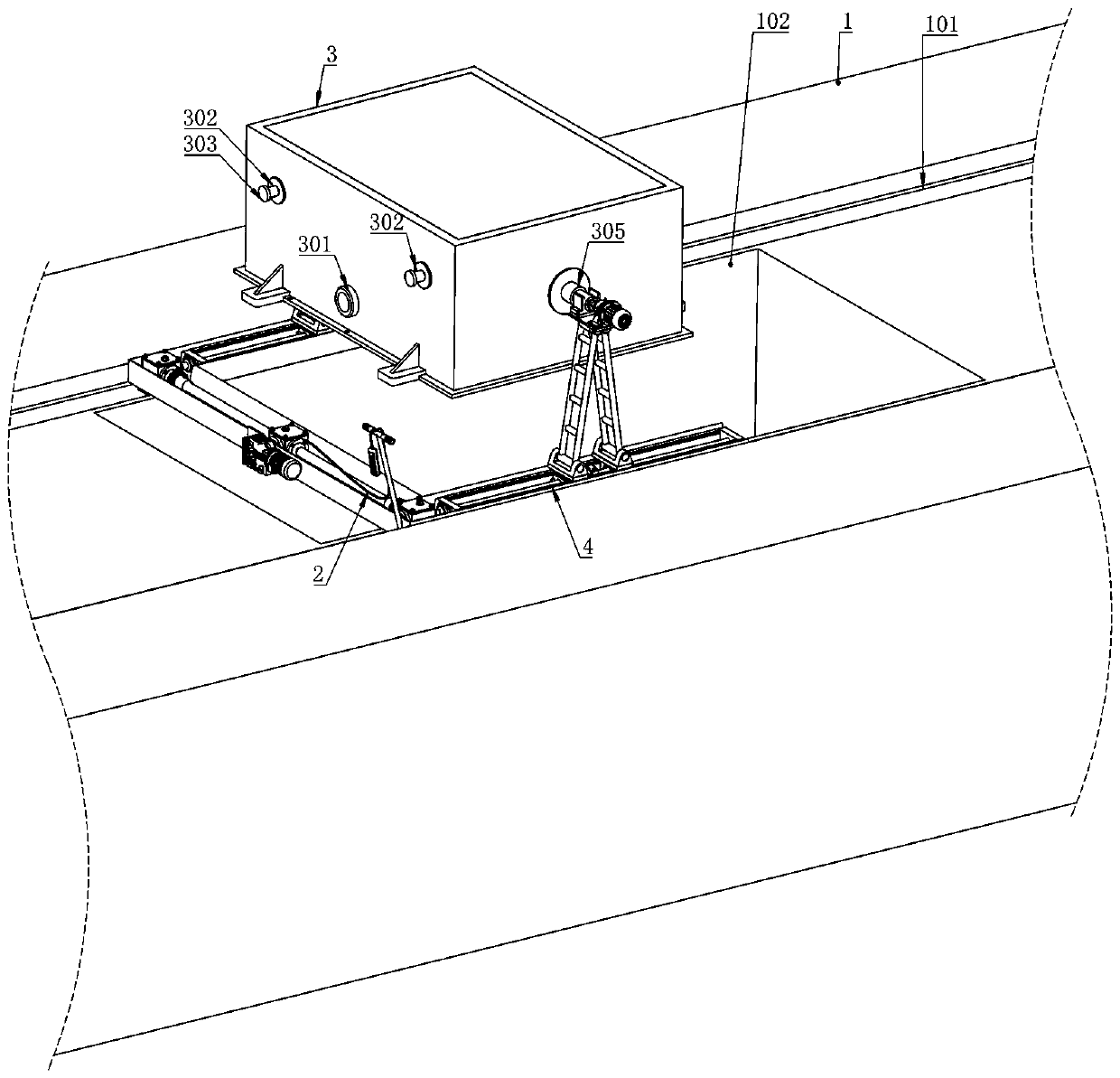
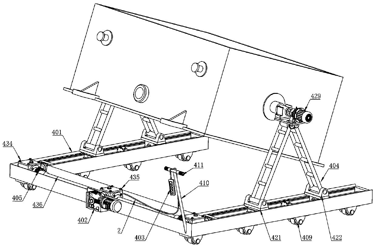
[0013] The technical problem to be solved by the present invention is to provide a V-method molding production line for the above-mentioned technical deficiencies, which adopts the design of a fast-moving demoulding device, and only needs to move the bracket to the turning axis through the handle when turning the mold. At the bottom, start the lifting motor to lift the mold box to a certain height. At this time, the mold box can be consigned to the casting area, and the lifting motor can be reversed to put down the mold box; Control the overturning angle of the mold box, thereby realizing the mold turning action; when the mold box is lifted, it can be dragged to the area of ​​the mold lifting platform in a straight line, so that the lifting and lowering of the mold box can be controlled by the lifting motor, and the mold lifting action can be coordinated ;During the entire mold making process, there is no need to hang and transport the mold box multiple times, which saves time and effort and has high work efficiency. The problem of time-consuming and labor-intensive work and low work efficiency is that the machine carries out multiple suspension transfers

Method used


Image

  • V-process production line
  • V-process production line
  • V-process production line

Examples


specific Embodiment approach 1

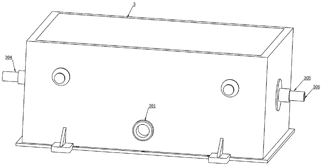
[0035] Specific implementation mode one: combine Figure 1-9As shown, a V-method molding production line is characterized in that: it includes a cement surface 1, a cable 2, a mold box 3 and a fast-moving demoulding device 4; a casting port 301 is provided through the lower part of the front side of the mold box 3; A lifting column 302 is fixedly arranged above the middle of the front and rear sides of the mold box 3; a stopper 303 is provided at one end of the lifting column 302; a slide rail 101 is provided at the middle of the cement surface 1 in the length direction; the fast moving The demoulding device 4 is arranged inside the slide rail 101; the middle part of the cement surface 1 is provided with a mold groove 102 between the slide rails 101; the fast moving demoulding device 4 includes a track base 401, a lifting motor 402, Control handle switch 403, lifting frame 404, coupling 405, transmission key block 406 and support 425; both sides of the track base 401 are provi...


PUM


Abstract

The invention relates to the technical field of casting, in particular to a V-process production line. The V-process production line comprises the design of a quick movable demolding device, when a mold is turned over, only a bracket needs to be moved below a turnover shaft by virtue of a grip, a lifting motor is started so as to lift a mold box to a certain height, the mold box can be conveyed toa mold casting area at the moment, and the lifting motor is reversed so as to put down the mold box; the mold box is lifted after a mold is sealed, and the turnover angle of the mold box can be controlled by a turnover motor, so that the mold turnover operation is realized; the mold box can be linearly pulled to the area of a mold lifting platform in a lifting state, so that the lifting and lowering operation of the mold box can be controlled by the lifting motor, and the mold lifting operation is matched; and the mold box does not need to be hung and conveyed for many times in the whole moldmanufacturing process, so that time and labor are saved, the working efficiency is high, and the problems of time and labor consumption and low working efficiency because the mold box needs to be hung and conveyed for many times by the lifting motor when a sand box is put and turned over and the mold is lifted and the sand box is put on the mold lifting platform are solved.

Description

technical field [0001] The invention relates to the technical field of casting, in particular to a V-method molding production line. Background technique [0002] V-method casting uses plastic film to seal the sand box, and the air in the mold is drawn out by the vacuum pumping system. There is a pressure difference between the inside and outside of the mold, which makes the dry sand dense and forms the required cavity. The casting is solidified, the negative pressure is released, and the molding sand collapses to obtain the casting. [0003] The processing process is to cover the softened film on the surface of the model, and make the film close to the surface of the model under the vacuum suction of 200-400mmHg through the air hole. [0004] (1) put the sand box [0005] After the paint is sprayed and dried (it is not required in the process), the special sand box is placed on the model covered with film. [0006] (2) Add sand and vibrate [0007] Add dry sand with bet...

Claims


Application Information

Patent Timeline
Patent Type & Authority Applications(China)
IPC IPC(8): B22C25/00B22C9/03B22C19/00B66F19/00
CPCB22C9/03B22C19/00B22C25/00B66F19/00
Inventor 佘凯陈志涛马士杰
Owner DINGZHOU DONGFANG FOUNDRY
Learn More