
Light-emitting device transfer printing method and light-emitting device transfer printing system

A light-emitting device and transfer printing technology, which is applied in the direction of electric solid-state devices, semiconductor devices, electrical components, etc., can solve the problems of consistent force, microLED cannot be accurately placed in the target area, transfer yield, and microLED is difficult to accurately transfer, so as to improve The effect of yield

Active Publication Date: 2022-01-25
SHENZHEN CHINA STAR OPTOELECTRONICS SEMICON DISPLAY TECH CO LTD
View PDF6 Cites 0 Cited by
  • Summary
  • Abstract
  • Description
  • Claims
  • Application Information

AI Technical Summary

Problems solved by technology

[0003] During the research and practice of the existing technology, the inventors of the present application found that when transferring a large number of microLEDs at the same time, since the transfer head cannot exert the same force on each LED, some microLEDs may not be positioned accurately. In the target area, the transfer yield drops
As for the laser transfer technology, due to the influence of the size of the spot, it is difficult to accurately transfer the micro LED with a smaller size.

Method used


Image

  • Light-emitting device transfer printing method and light-emitting device transfer printing system
  • Light-emitting device transfer printing method and light-emitting device transfer printing system
  • Light-emitting device transfer printing method and light-emitting device transfer printing system

Examples


Embodiment Construction

[0035] The following will clearly and completely describe the technical solutions in the embodiments of the application with reference to the drawings in the embodiments of the application. Apparently, the described embodiments are only some of the embodiments of the application, not all of them. Based on the embodiments in this application, all other embodiments obtained by those skilled in the art without making creative efforts belong to the scope of protection of this application. In addition, it should be understood that the specific implementations described here are only used to illustrate and explain the present application, and are not intended to limit the present application. In this application, unless stated to the contrary, the used orientation words such as "up" and "down" usually refer to up and down in the actual use or working state of the device, specifically the direction of the drawing in the drawings ; while "inside" and "outside" refer to the outline of ...


PUM

PropertyMeasurementUnit
thicknessaaaaaaaaaa
thicknessaaaaaaaaaa

Abstract

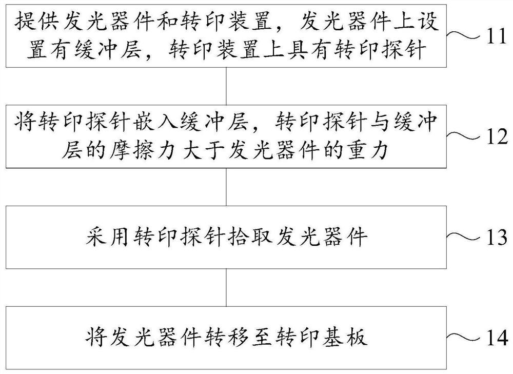
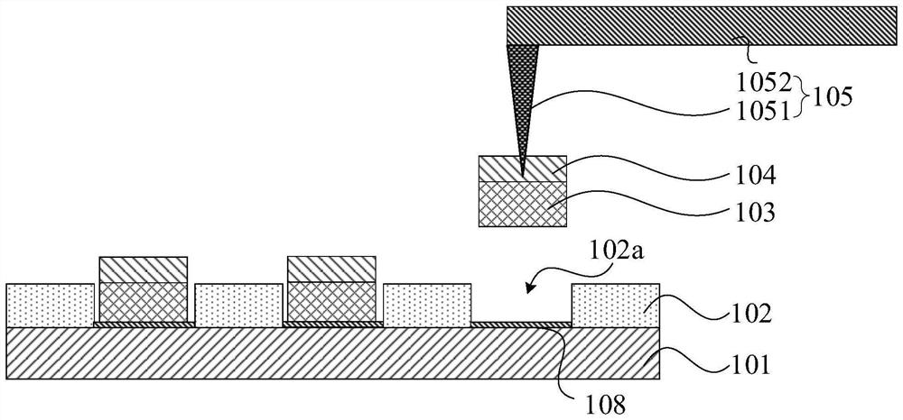
The embodiment of the invention discloses a light-emitting device transfer printing method and a light-emitting device transfer printing system. A buffer layer is added on a light-emitting device, and a transfer printing probe is embedded into the buffer layer to pick up the light-emitting device for transfer printing. Since the transfer printing probe is embedded into the buffer layer on the light-emitting device to transfer the light-emitting device, the problem of uneven stress of each light-emitting device does not exist. Therefore, the light-emitting device can be accurately arranged in the target area, and the transfer yield of the light-emitting diode is further improved. In addition, the transfer printing probe in the light-emitting device transfer printing method provided by the embodiment of the invention can be a micro-nano probe. The probe body of the micro-nano probe is small, and transfer printing can be carried out on a micro light-emitting diode or a mini light-emitting diode. The micro-nano probe is adopted for transfer printing, the situation that the light-emitting device is difficult to adsorb due to too small adsorption force under the condition that the precision of a transfer probe adopting vacuum adsorption is small can be avoided, and then the light-emitting device is kept stable in the transfer process.

Description

technical field [0001] The present application relates to the field of display technology, in particular to a method for transferring a light-emitting device and a system for transferring a light-emitting device. Background technique [0002] As a representative of new display technology, micro-light-emitting diode (microLED) display has attracted widespread attention in the industry due to its advantages such as high brightness, high contrast, wide color gamut, fast response and high reliability. However, microLED technology faces many challenges, among which mass transfer is one of the most core technologies. At present, mass transfer methods include electrostatic force, van der Waals force, laser, fluid self-assembly, etc., and the mainstream technologies are Stamp transfer and laser transfer. For Stamp transfer technology, both the attraction and release between the transfer head and the LED are controlled by van der Waals forces. [0003] During the research and pract...

Claims


Application Information

Patent Timeline
Patent Type & Authority Applications(China)
IPC IPC(8): H01L27/15H01L33/00H01L33/62
CPCH01L27/156H01L33/0093H01L33/62
Inventor 段淼陈黎暄
Owner SHENZHEN CHINA STAR OPTOELECTRONICS SEMICON DISPLAY TECH CO LTD
Learn More