Low-nitrogen oxide combustor

A low-nitrogen oxide, burner technology, applied in burners, gas fuel burners, combustion methods, etc., can solve the problem of insignificant NOx emission effect, and achieve stable combustion performance, lower combustion temperature, and lower NOx emissions. Effect

Pending Publication Date: 2019-10-01
GUANGDONG VANWARD NEW ELECTRIC CO LTD
View PDF0 Cites 1 Cited by
  • Summary
  • Abstract
  • Description
  • Claims
  • Application Information

AI Technical Summary

Problems solved by technology

[0003] The present invention provides a low-nitrogen oxide burner to overcome the problem that existing burners with simple structures have no obvious effect on reducing NOx emissions.

Method used


Image

  • Low-nitrogen oxide combustor
  • Low-nitrogen oxide combustor
  • Low-nitrogen oxide combustor

Examples


Embodiment 1

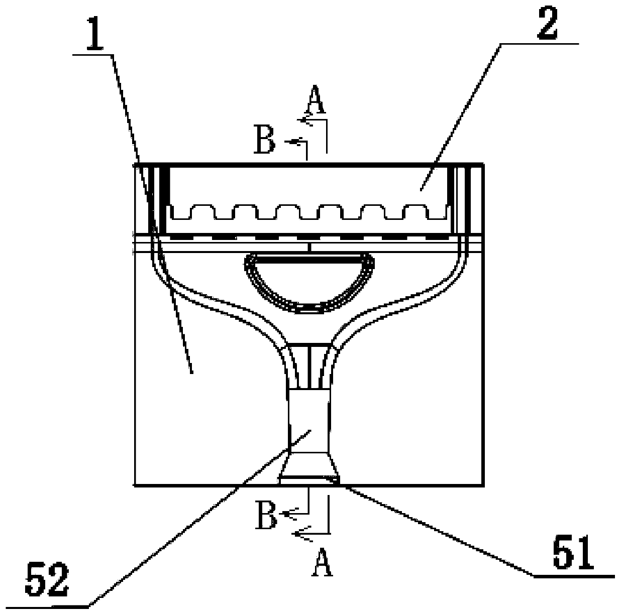
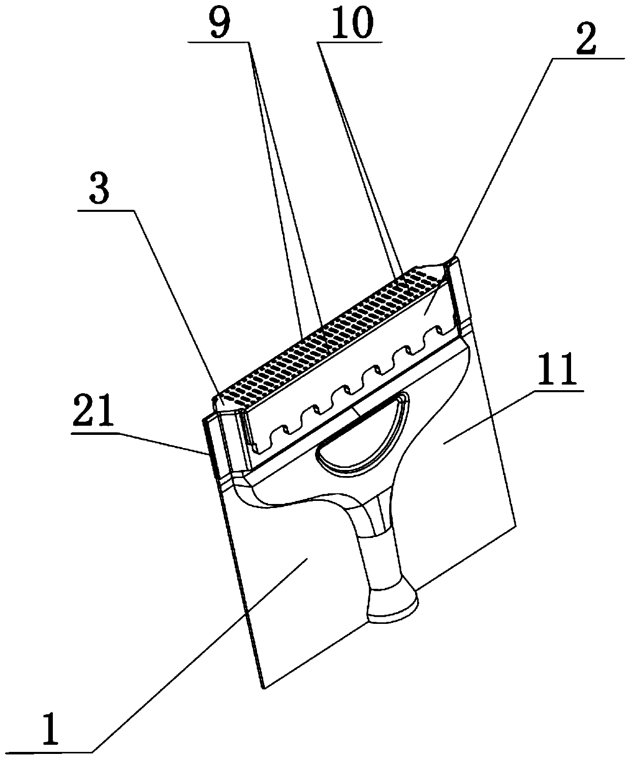
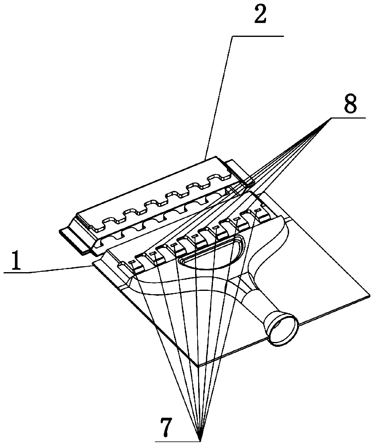
[0029] Such as Figure 1 to Figure 8As shown, a low nitrogen oxide burner includes an inner shell 1 and an outer shell 2 installed outside the inner shell 1, one end of the outer shell 2 is provided with a fire hole plate 3, and a dense flame is formed between the outer shell 2 and the inner shell 1 Channel 4; the inner shell 1 is formed with a premixed channel 5 and a thin flame channel 6 which communicate with each other, and the inner shell 1 is provided with a thick flame premixed gas inlet 7 which communicates with the premixed channel 5 and the thick flame channel 4, and the inner shell 1 A secondary air inlet 8 through which outside air enters into the light flame passage 6 is arranged on the top; a number of thick fire holes 9 connected to the thick flame passage 4 and a number of light fire holes 10 connected to the light flame passage 6 are arranged on the fire orifice plate 3; The premix channel 5 is vertically upward and forms a "T" shape with the fire orifice plat...

Embodiment 2

[0040] The difference from Example 1 is that, as Figure 8 As shown, one end of the shell 2 can also replace the fire hole plate 3 by installing a fire hole core 14. The fire hole core 14 is a structure formed by a number of stainless steel plates arranged at intervals. A gas channel is formed between several stainless steel plates and formed at the top Light fire hole 10, the top of thick flame passage 4 forms thick fire hole 9.

[0041] working principle:

[0042] The gas is injected into the injection section 51 of the premixing channel 5 at a certain pressure, and the air outside the burner is drawn into the premixing channel 5 and fully mixed in the mixing section 52 to become a premixed gas of gas and air, such as Figure 5 As shown, the premixed gas is divided into three gas paths, of which the left and right two gas paths enter the left and right thick flame passages 4 through the thick flame premixed gas inlet 7, and then burn in the thick flame hole 9 to form a thic...


PUM


Abstract

The invention discloses a low-nitrogen oxide combustor which comprises an inner shell and an outer shell installed on the outer side of the inner shell. One end of the outer shell is provided with a fire hole plate or provided with a fire hole core, and a thick flame channel is formed between the outer shell and the inner shell. A pre-mixing channel and a thin flame channel which communicate witheach other are formed in the shell, a thick flame pre-mixing gas inlet communicating with the pre-mixing channel and the thick flame channel is formed in the inner shell, and a secondary air inlet forexternal air to enter the thin flame channel is formed in the inner shell. The pre-mixing channel is upwards vertical and forms a T shape with the fire hole plate. By means of the low-nitrogen oxidecombustor, diversion of thick flames and thin flames is achieved, the problem that a combustor simple in structure in the existing industry is not obvious in NOx emission effect is solved, NOx emission is effectively controlled through a single-injection channel, and meanwhile NOx emission is effectively controlled through a T-shaped single-injection channel. By means of the low-nitrogen oxide combustor, the structure and forming are simple, the size is convenient to control, the cost is low, and the combustion performance is stable.

Description

technical field [0001] The present invention relates to the technical field of burners, in particular to a low nitrogen oxide burner. Background technique [0002] Today, my country's economic development has achieved world-renowned achievements, but the problem of environmental pollution has become increasingly prominent, posing a great threat to the sustainable development of my country and the world economy. In order to improve the quality of economic development and better coordinate the relationship between development and the environment, in the prevention and control of In terms of air pollution, the country has formulated a series of emission reduction measures, especially in the field of gas water heaters. Low-carbon and low NOx emissions have become a matter of great concern to our country and even countries around the world. At present, major gas water heater manufacturers only reduce CO emissions. Not enough attention has been paid to NOx emissions. Under the backg...

Claims


Application Information

Patent Timeline
IPC IPC(8): F23D14/04F23D14/62F23L9/00
CPCF23D14/04F23D14/62F23L9/00
Inventor 卢楚鹏唐元锋李罗标张上兵潘同基
Owner GUANGDONG VANWARD NEW ELECTRIC CO LTD
Why Eureka
Try Eureka