
Water distributing device of wastewater treatment and pulse type water distributing method thereof

A water distribution device and wastewater treatment technology, applied in biological water/sewage treatment, water/sludge/sewage treatment, anaerobic digestion treatment, etc. Increase the mixing effect of mud and water and the effect of sufficient anaerobic reaction of wastewater

Inactive Publication Date: 2019-10-01
ANHUI SHENGNUOBEI CHEM TECH
View PDF7 Cites 1 Cited by
  • Summary
  • Abstract
  • Description
  • Claims
  • Application Information

AI Technical Summary

Problems solved by technology

[0005] Aiming at the problem that the pulse water distribution method and pulse frequency are too single in the existing chemical wastewater treatment equipment, the present invention provides a water distribution device for wastewater treatment and a pulse water distribution method

Method used


Image

  • Water distributing device of wastewater treatment and pulse type water distributing method thereof
  • Water distributing device of wastewater treatment and pulse type water distributing method thereof
  • Water distributing device of wastewater treatment and pulse type water distributing method thereof

Examples


Embodiment 1

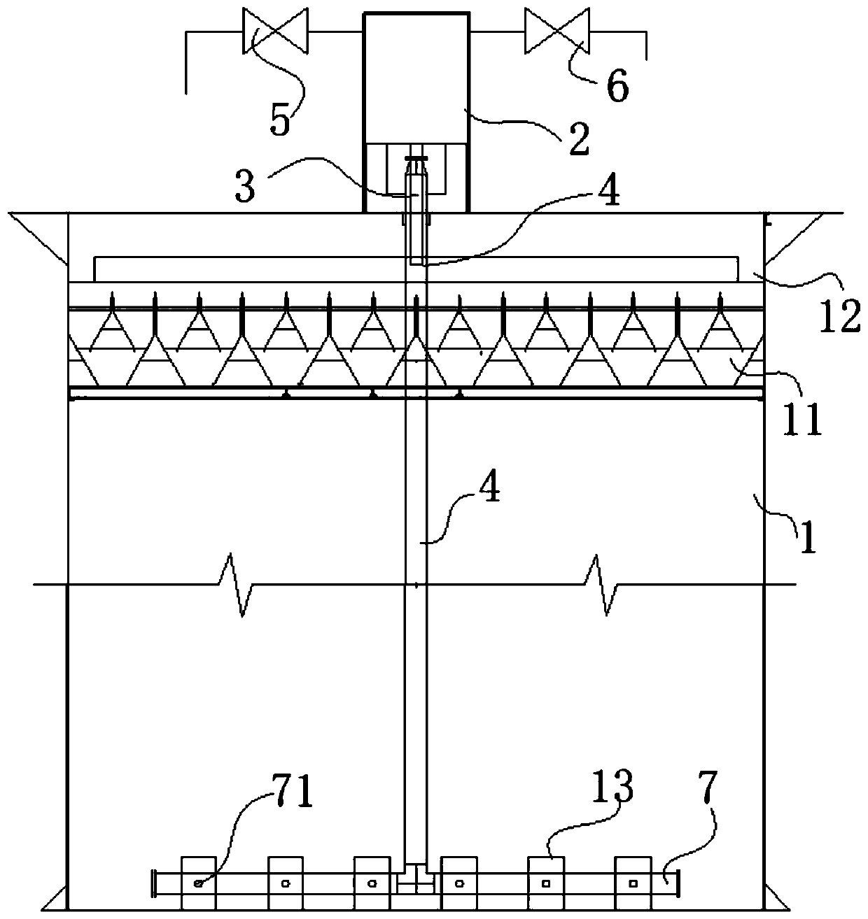
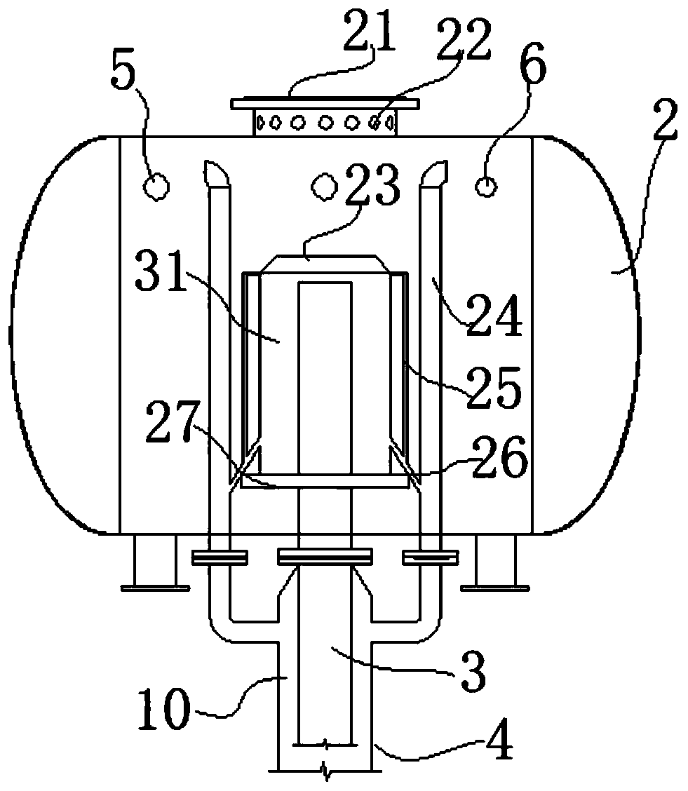
[0039] A water distribution device for wastewater treatment in this embodiment, such as figure 1 , 2As shown in . The main siphon 3, the upper part of the main siphon 3 is covered with an inverted barrel-shaped cover 23 to realize a closed space, and the lower end passes through the tank body and is inserted into the upper part of the main water distribution pipe 4 to form a pipe-in-pipe casing structure. The cover body 23 is fixed by a fixing plate 27, and the fixing plate 27 is fixed on the inner wall of the tank body; a ring cavity 31 is formed between the inside of the cover body 23 and the main siphon pipe 3, and the ring cavity 31 is externally connected with a vacuum breaking tube 28. The vacuum breaking pipe 28 is in an inverted "L" shape, and forms a siphon structure with the main siphon pipe 3. Under the action of hydraulic force, a certain degree of vacuum can be generated inside the cover body 23 to realize pulse water distribution; the main water distribution pip...

Embodiment 2

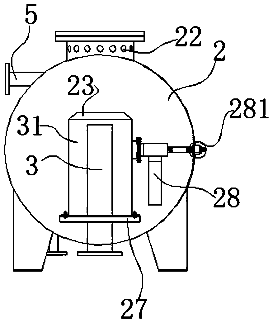
[0042] A water distribution device for wastewater treatment in this embodiment is further improved on the basis of Embodiment 1, such as image 3 As shown, after the upper part of the vacuum breaking tube 28 passes through the rotating shaft to the outside of the tank, a rotatable adjustment handle 281 is externally connected to the rotating shaft to rotate the vacuum breaking tube 28, and the rotation can be realized manually or electrically, that is, the vacuum breaking tube 28 By adjusting the handle 281 to realize swinging back and forth, it is not only beneficial to adjust the water distribution volume and pulse frequency, but also further increases the mixing effect of hydraulic agitation, that is, by adjusting the height and low of the vacuum breaking tube 28, different pulse frequencies and water distribution volumes can be adjusted to achieve Requirements for processing capacity under different working conditions.

[0043] The pulse type water distribution method of t...

Embodiment 3

[0048] A water distribution device for wastewater treatment in this embodiment is further improved on the basis of Embodiment 2, such as figure 2 As shown, between the bottom of the main siphon pipe 3 and the casing structure on the upper part of the main water distribution pipe 4, an annular gas collection chamber 10 with a top seal is formed, and the upper part of the gas collection chamber 10 is externally connected to an exhaust pipe 24, and the exhaust pipe After the top of 24 is inserted into the tank, until the top of the tank is higher than the top of the cover body 23, the breathing end of the siphon structure is formed, and the waste gas in the main water distribution pipe 4 can also be discharged; the gas collection chamber 10 is located in the pulse water distributor 2. The 4 main water distribution pipes at the bottom can quickly collect the exhaust gas in the water distribution pipe, and discharge the excess gas in time through the connected exhaust pipe 24, so t...


PUM


Abstract

The invention discloses a water distributing device of wastewater treatment and a pulse type water distributing method thereof, and belongs to the field of wastewater treatment devices. The water distributing device comprises an anaerobic reactor and a pulse water distributor fixed to the top of the anaerobic reactor. The body of the pulse water distributor is a horizontal tank body. The upper portion of the pulse water distributor is externally connected with a wastewater inlet pipe. A main siphon pipe is arranged in the pulse water distributor. The upper portion of the main siphon pipe is covered with an inverted-barrel-shaped cover body. The lower end of the main siphon pipe penetrates out of the tank body and is then inserted in the upper portion of a main water distributing pipe. Thecover body is fixed through a fixing plate. An annular cavity is formed between the interior of the cover body and the main siphon pipe. The annular cavity is externally connected with a vacuum breaking pipe. The vacuum breaking pipe is in an inverted L shape. The vacuum breaking pipe and the main siphon pipe form a siphon structure. The bottom end of the main water distributing pipe is directly inserted in the bottom of the anaerobic reactor and communicated with a water distributing branch pipe transversely laid at the bottom of the anaerobic reactor. The upper portion of the vacuum breakingpipe penetrates out of the tank body through a rotating shaft and is then externally connected with a rotatable adjusting handle through the rotating shaft. The aim of pulse water distributing can berealized by rotating the vacuum breaking pipe, and the frequency can be adjusted.

Description

technical field [0001] The invention belongs to the field of waste water treatment equipment, and more specifically relates to a water distribution device for waste water treatment and a pulsed water distribution method thereof. Background technique [0002] A large amount of wastewater will be produced in chemical production. The wastewater with high and medium concentration is often treated anaerobically. Currently, the most widely used is the USAB reactor (upflow anaerobic sludge bed method). The good operation of the oxygen reactor is very important, and the water inlet system has the functions of water distribution and hydraulic stirring. At present, the commonly used water inlet methods can be divided into intermittent type (pulse type), continuous type, continuous and intermittent combination type; from the form of water distribution pipes, there are one tube with multiple holes, one tube with one hole and branched: continuous water intake mode (one One hole in the p...

Claims


Application Information

Patent Timeline
Patent Type & Authority Applications(China)
IPC IPC(8): C02F3/28
CPCC02F3/2866C02F3/28
Inventor 董波尹星
Owner ANHUI SHENGNUOBEI CHEM TECH
Learn More