Auxiliary tool for installing synchronous wheel on servo motor

An auxiliary tool, servo motor technology, applied in the direction of electromechanical devices, manufacturing tools, manufacturing motor generators, etc., can solve the problems of motor damage, motor casing crushing, etc., to prevent crushing, good buffering, and reduce pressure. Effect

Inactive Publication Date: 2019-09-27
扬州格莱特电动工具有限公司
View PDF4 Cites 2 Cited by
  • Summary
  • Abstract
  • Description
  • Claims
  • Application Information

AI Technical Summary

Problems solved by technology

[0005] The purpose of the present invention is to solve the shortcomings in the prior art, such as: when the existing auxiliary tool for installing the synchronous wheel of the servo motor uses a manipulator to clamp the synchronous wheel, the manipulator is easy to move the motor due to excessive downward pressure. The casing is crushed, causing damage to the motor

Method used


Image

  • Auxiliary tool for installing synchronous wheel on servo motor
  • Auxiliary tool for installing synchronous wheel on servo motor
  • Auxiliary tool for installing synchronous wheel on servo motor

Examples


Embodiment 1

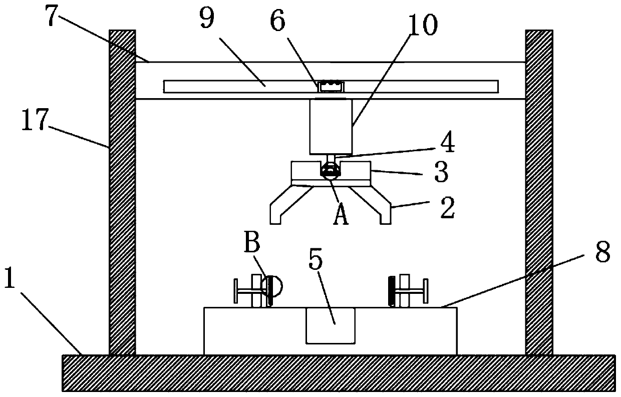
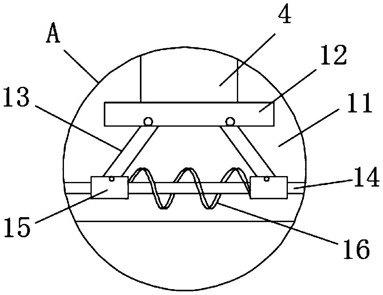
[0027] refer to Figure 1-4 , an auxiliary tool for installing synchronous wheels for servo motors, including a base 1, a magnetic column 5 is fixedly installed at the center of the upper end surface of a placement table 8, and the magnetic column 5 has a guiding effect on the placement of the motor, and has a good effect on the motor Adsorption effect, the upper side wall of the base 1 is fixedly connected with a placement table 8, the upper side wall of the base 1 is connected with a mounting plate 7 through a support device, the support device includes two support plates 17, and each support plate 17 is fixedly connected On the base 1 , each support plate 17 is fixedly connected with the installation plate 7 , and the support plates 17 have a supporting effect on the installation plate 7 .

[0028] There is a sliding cavity 9 in the mounting plate 7, and the inner wall of the sliding cavity 9 is connected with a moving plate 10 through a sliding device. The sliding device i...

Embodiment 2

[0033] Embodiment 2 differs from Embodiment 1 in that it is an auxiliary tool for installing synchronous wheels for servo motors. Placement has a guiding effect and has a good adsorption effect on the motor. The upper side wall of the base 1 is fixedly connected with a placement table 8, and the upper side wall of the base 1 is connected with a mounting plate 7 through a supporting device. The supporting device includes two supporting devices. Plates 17 , each support plate 17 is fixedly connected to the base 1 , each support plate 17 is fixedly connected with the installation plate 7 , and the support plates 17 have a supporting effect on the installation plate 7 .

[0034] There is a sliding cavity 9 in the mounting plate 7, and the inner wall of the sliding cavity 9 is connected with a moving plate 10 through a sliding device. The sliding device includes a moving block 6, and one end of the moving block 6 is fixedly connected to the moving plate 10, and the moving block 6 de...


PUM


Abstract

The invention discloses an auxiliary tool for installing a synchronous wheel on a servo motor, and the auxiliary tool comprises a base, wherein the upper side wall of the base is connected with a mounting plate through a supporting device, and a sliding cavity is formed in the mounting plate; the inner wall of the sliding cavity is connected with a moving plate through a sliding device, and the moving plate is connected to the bottom side wall of the mounting plate in a sliding mode. According to the invention, when a telescopic rod is lengthened to press a telescopic block, the telescopic block presses a manipulator body downwards, and the manipulator body can press downwards and clamps the synchronous wheel; at the moment, the telescopic rod can continue to press a fixing plate downwards, and a rotating rod is pressed down; therefore, a first spring is lengthened, and the pressure of the telescopic rod is converted into the elastic potential energy of the first spring, so that the pressure of the telescopic block on the manipulator body is reduced, and the manipulator body is buffered, thereby avoiding the situation that a motor shell is crushed by the mechanical arm body due to overlarge downward pressure as much as possible, and avoiding the waste of resources.

Description

technical field [0001] The invention relates to the technical field of motors, in particular to an auxiliary tool for installing a synchronous wheel of a servo motor. Background technique [0002] Motor (English: Electric machinery, commonly known as "motor") refers to an electromagnetic device that realizes the conversion or transmission of electric energy according to the law of electromagnetic induction. In the circuit, it is represented by the letter M (the old standard is D). Its main function is to generate driving torque as a power source for electrical appliances or various machinery. A generator is represented by the letter G in the circuit. Its main function is to convert mechanical energy into electrical energy. At present, the most commonly used is to use heat energy, water energy, etc. to drive the rotor of the generator to generate electricity. In addition to motors, they can be divided into stepless constant speed motors, stepless constant speed motors, and ...

Claims


Application Information

Patent Timeline
Patent Type & Authority Applications(China)
IPC IPC(8): H02K15/00B23P19/02
CPCB23P19/02H02K15/00
Inventor 吴明林
Owner 扬州格莱特电动工具有限公司
Why Eureka
Try Eureka