
An active shield machine telescopic swing system

A telescopic swing and shield machine technology, applied in mining equipment, tunnels, earth-moving drilling, etc., to achieve the effect of reducing the difficulty of tool change, simple structure, and reducing the probability of failure

Active Publication Date: 2020-06-16
ZHEJIANG UNIV
View PDF11 Cites 0 Cited by
  • Summary
  • Abstract
  • Description
  • Claims
  • Application Information

AI Technical Summary

Problems solved by technology

There is no domestic patent explaining the hydraulic working principle of the anti-twist cylinder of the shield machine

Method used


Image

  • An active shield machine telescopic swing system
  • An active shield machine telescopic swing system
  • An active shield machine telescopic swing system

Examples


Embodiment 1

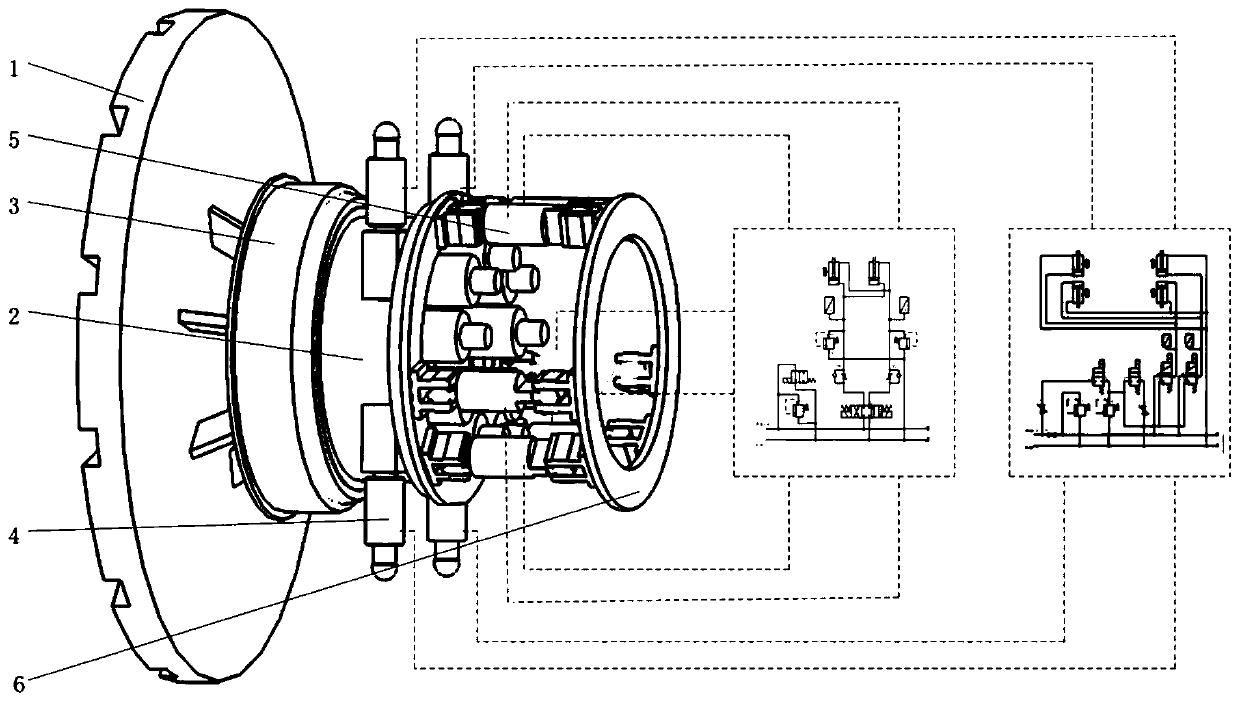
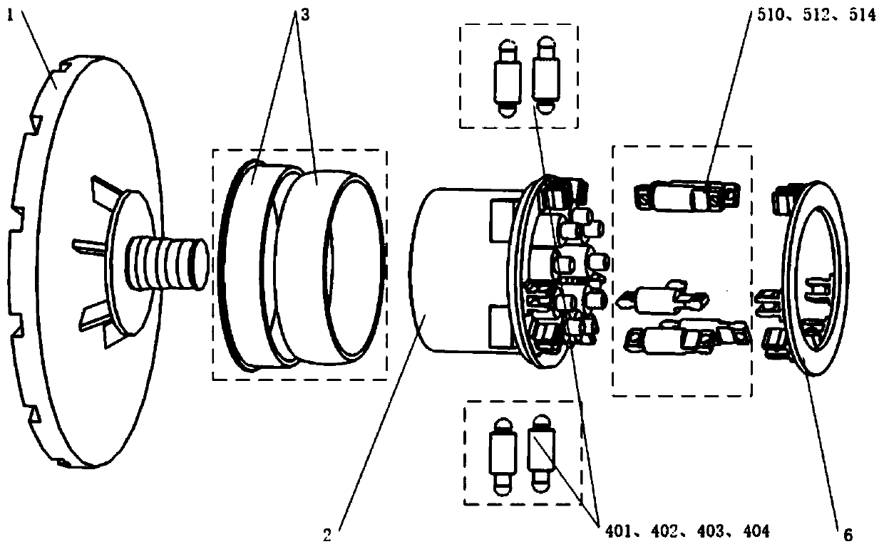
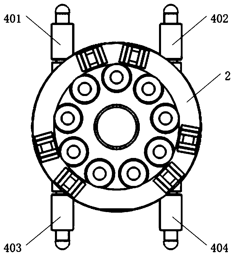
[0035] During the forward excavation process of the shield machine, the cutter head 1 rotates clockwise to cut the hard rock and soil layer, and is subjected to the reaction force of the working face. The reaction force is transmitted to the cutter head drive module 2, driving the cutter head drive module 2 to rotate counterclockwise in the shield body, and at the same time, the second two-position three-way reversing valve 49 in the anti-torque subsystem 4 is energized to activate the second torque Oil cylinder 402 and the third torque oil cylinder 403. The first torque oil cylinder 401 and the fourth torque oil cylinder 404 are in a passive state. The nature of the rock and soil working face is unstable, and the reaction force received by the cutter head 1 is also unstable. According to the difference in the displacement sensor signal of the torque cylinder in the passive state and the active state, the first two-position two-way reversing valve and the second two-position t...

Embodiment 2

[0037] During the forward tunneling process of the shield machine, the cutter head 1 continues to cut the hard rock and soil until the tool wears out and the maintenance engineer needs to replace the tool. The operator controls the telescopic swing subsystem 5 through the operation panel in the control room, retracts three sets of telescopic swing cylinders synchronously, and the telescopic swing cylinder drives the cutter head drive module 2 and the cutter head 1 to retract, thereby leaving a space in front of the cutter head 1. A certain amount of space is convenient for maintenance engineers to enter the space to check and replace tools. The maintainer returns to the shield body after replacing the tool and confirming that it is correct. The operator controls the telescopic swing subsystem 5, and synchronously extends three sets of telescopic swing cylinders, and the telescopic swing cylinders drive the cutter head drive module 2 and the cutter head 1 to extend to the origi...


PUM


Abstract

The invention relates to an active shield tunneling machine telescopic oscillating system, which comprisesa cutterhead, a cutterhead driving module, a ball bearing, an anti-kink system, a telescopic oscillating subsystem, and acapstan. The tail end of the cutterhead is connected to the inside of the cutterhead driving module; the cutterhead driving module is of a movable structure; the inner ring of the ball bearing is fixed to the cutterhead driving module, and the outer ring is fixedly connected with a shield body; one ends of four torque oil cylinders in the anti-kink system are fixed toa corner of the cutterhead driving module, the other endsare fixed to the shield body, an internal hydraulic control component is placed at the rear of the shield body and connected with the torque oil cylinders through hydraulic pipelines; the telescopic oscillating subsystem comprises six telescopic oscillating oil cylinders which are fixed between the cutterhead driving module and the capstan, and the capstan is fixedly connected with the shield body. The active shield tunneling machine telescopic oscillating system is used for cutterhead tool change and shield body escape, and efficiency and safety of shield constructioncan be effectively improved.

Description

technical field [0001] The invention relates to a fluid pressure execution system, in particular to an active shield machine telescopic swing system. Background technique [0002] Since the 21st century, the construction of urban rail transit in my country has developed rapidly. Many first- and second-tier cities have attached great importance to the construction of subway tunnels, in which shield tunneling plays an important role. At present, shield tunneling is developing in the direction of comprehensive mechanization, automation, and intelligence, and it is applied to harsh working conditions with large depths, long distances, special sections, and special shapes. Severe operating conditions put forward more stringent requirements for the design and manufacture of shield tunneling machines. During long-distance excavation, the shield cutting tool will continue to wear out as the excavation distance increases until the damage fails. The geology of our country is complex...

Claims


Application Information

Patent Timeline
Patent Type & Authority Patents(China)
IPC IPC(8): E21D9/06E21D9/08E21D9/093
CPCE21D9/06E21D9/08E21D9/093
Inventor 魏建华张杭军胡惠兵冯瑞琳吴凯瑞熊磊戴天文郭豪
Owner ZHEJIANG UNIV
Learn More