Building protection shed convenient to transport and capable of ascending and descending

A technology for protective sheds and buildings, which is applied to buildings, small buildings, building types, etc., can solve problems such as poor anti-smashing effect, weak protective sheds, and inability to use flexibly, and achieves the effect of enhancing stability and facilitating transportation and storage.

Inactive Publication Date: 2019-09-27
FUNAN GAOFUXING INTELLIGENT TECH CO LTD
View PDF1 Cites 2 Cited by
  • Summary
  • Abstract
  • Description
  • Claims
  • Application Information

AI Technical Summary

Problems solved by technology

[0002] In the process of building construction, carpentry, steel reinforcement, mixing and other constructions are often required. These operations are generally carried out near the building. During the construction process near the building, objects may fall from the air at any time and cause injury to the construction personnel. , damage to construction equipment
In order to achieve safe construction, at present, the construction site generally adopts steel pipes, angle steel and other materials to weld the frame, and put wooden boards and other protective plates on the top of the frame to make a simple protective shed. This protective shed has the following disadvantages: 1. Welding and welding and cutting are required during installation and disassembly, which is labor-intensive; 2. After dismantling, steel pipes, angle steel and other materials become scrap iron and steel, which cannot be reused, causing great waste and increasing construction costs; 3. The protective shed itself It is not firm, and the anti-smashing effect is poor in actual use, and it cannot effectively protect the safety of workers, pedestrians or vehicles under the shed; 4. It cannot be used flexibly. When the work site moves, the installed protective shed will lose its function and must be dismantled. re-install
[0003] For example, a new type of mobile tunnel building protective shed provided by Chinese patent application number CN201820635435.7 includes support columns on both sides, and the bottoms of the support columns on both sides are welded with feet, and the inner cavities of the feet on both sides are Three groups of buffer springs are installed, and a control button is installed in the middle of the front side of the supporting column on the right side, and a beam is welded in the middle of the supporting columns on both sides, and a motor box is welded in the middle of the front side of the beam. A motor is installed in the inner cavity of the motor box, and the transmission head at the rear end of the motor is installed through the bottom of the inner cavity of the beam. The transmission head at the rear end of the motor is equipped with a screw head, and the inner cavity of the beam is horizontally equipped with a rotating shaft. The middle part of the rotating shaft is fitted with a transmission gear. During the construction of the tunnel, the space is narrow, which is not conducive to the construction of the protective shed. This new solution is easy to use, convenient to build, easy to install and disassemble, and has strong flexibility. It is very suitable for the construction of temporary protective sheds. Although the installation and disassembly of this kind of protective shed is convenient, each assembly needs to be reinstalled and locked every time the bucket is assembled, and the operation process is cumbersome and laborious

Method used


Image

  • Building protection shed convenient to transport and capable of ascending and descending
  • Building protection shed convenient to transport and capable of ascending and descending
  • Building protection shed convenient to transport and capable of ascending and descending

Examples


Embodiment Construction

[0024] The following will clearly and completely describe the technical solutions in the embodiments of the present invention with reference to the accompanying drawings in the embodiments of the present invention. Obviously, the described embodiments are only some, not all, embodiments of the present invention. Based on the embodiments of the present invention, all other embodiments obtained by persons of ordinary skill in the art without creative efforts fall within the protection scope of the present invention.

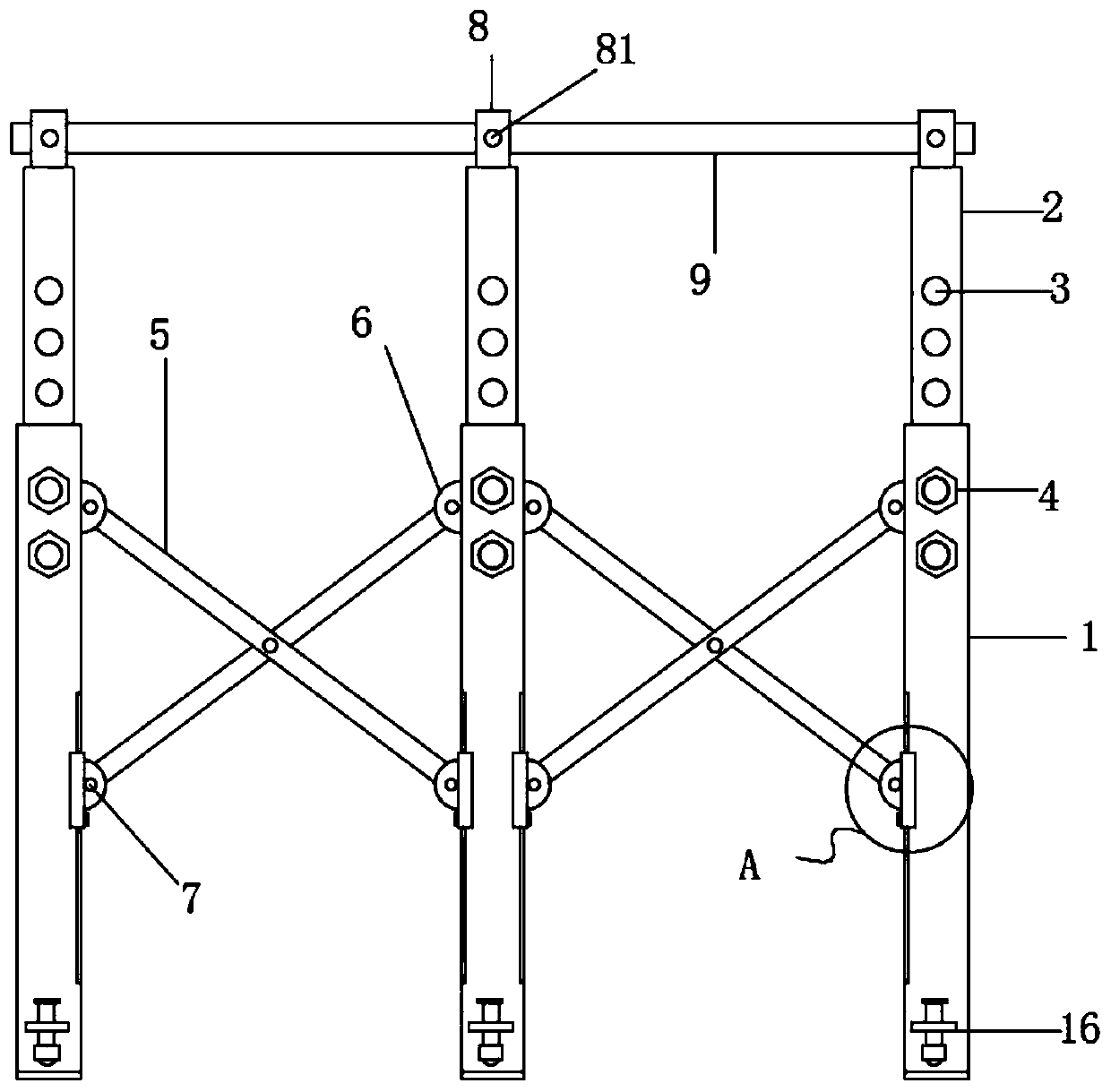
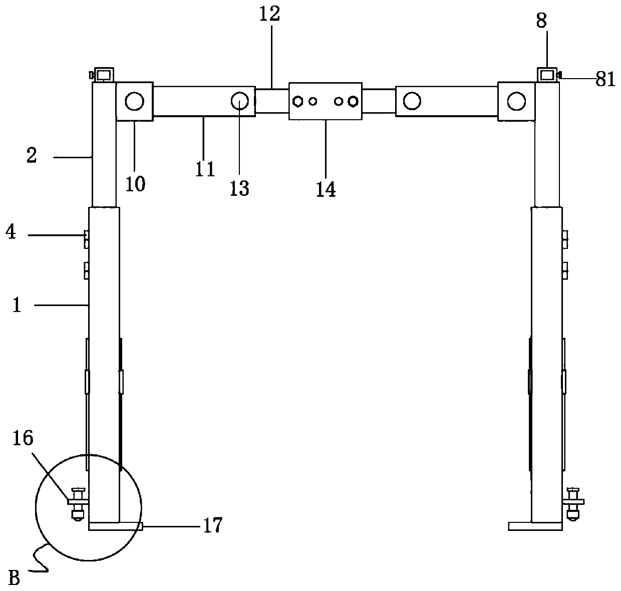
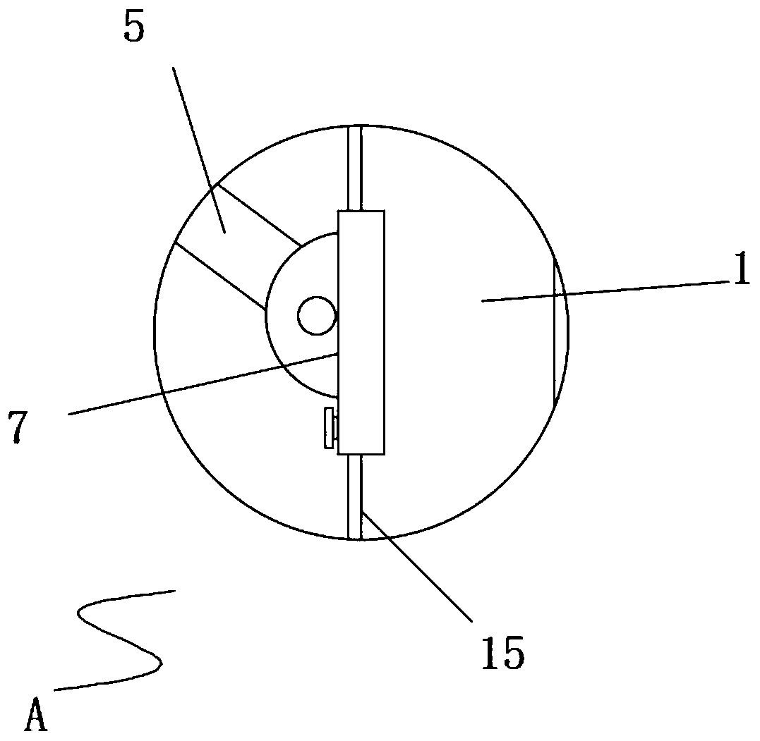
[0025] see Figure 1-7 , the present invention provides a technical solution: a building protective shed that is convenient for transportation and can be raised and lowered, including a fixed cover 1. The movable rod 2 is plugged in the inner movable, and the top of the movable rod 2 runs through the top of the fixed sleeve 1, and the limit hole 3 is evenly arranged on the movable rod 2, and the upper part of the fixed sleeve 1 is provided with a locking screw 4, b...


PUM


Abstract

The invention discloses a building protection shed convenient to transport and capable of ascending and descending in the technical field of building equipment. The building protection shed comprises a plurality of sets of fixing sleeves, wherein the multiple sets of fixing sleeves are divided into two rows in which the number is consistent front and back. The protection shed can achieve the lifting function, and the height of the protection shed can be adjusted according to the actual situation of the construction site. Through an arranged crossing rod piece mechanism and a locking mechanism, the stretching length of the protection shed can be controlled. Through the design, folding and drawing of the protection shed in the length direction can be achieved, in addition, the stretching length can be adjusted, and the protection shed can be arranged in the place where the space is narrow. Meanwhile, the stability of the protection shed is enhanced. Through an arranged telescopic sleeve and an arranged telescopic rod, the width of the protection shed can be adjusted; through arrangement of rotation connecting pieces, the protection shed can be folded and drawn in the width direction, and accordingly protection shed carrying and storing are convenient; and through arranged lifting wheels, the protection shed has movability.

Description

technical field [0001] The invention relates to the technical field of construction equipment, in particular to a conveniently transportable and liftable building protection shed. Background technique [0002] In the process of building construction, carpentry, steel reinforcement, mixing and other constructions are often required. These operations are generally carried out near the building. During the construction process near the building, objects may fall from the air at any time and cause injury to the construction personnel. , damage to construction equipment. In order to achieve safe construction, at present, construction sites generally use materials such as steel pipes and angle steel to weld frames, and put wooden boards and other protective plates on the top of the frame to make a simple protective shed. This protective shed has the following disadvantages: 1. Welding and welding and cutting are required during installation and disassembly, which is labor-intensi...

Claims


Application Information

Patent Timeline
IPC IPC(8): E04H1/12E04G21/32E04B1/343E04B1/344
CPCE04H1/1205E04G21/3204E04B1/3431E04B1/34336E04B1/34352E04B1/344E04B1/3441E04B1/34312E04B1/343
Inventor 不公告发明人
Owner FUNAN GAOFUXING INTELLIGENT TECH CO LTD
Why Eureka
Try Eureka