Dual-power-source vehicle-mounted tunnel lamp cleaning system

A dual power source and cleaning system technology, applied in road cleaning, cleaning methods, construction, etc., can solve the problems of easy accumulation of solid particles, poor low-speed stability, and influence on safe traffic, etc., to achieve improved cleaning efficiency, stable and uniform driving, and easy The effect of load control

Pending Publication Date: 2019-09-24
CHINA MERCHANTS CHONGQING COMM RES & DESIGN INST
View PDF0 Cites 2 Cited by
  • Summary
  • Abstract
  • Description
  • Claims
  • Application Information

AI Technical Summary

Problems solved by technology

[0002] Tunnel lighting is to solve the "black hole effect" or "white hole effect" caused by the sudden change of brightness when the vehicle enters or exits the tunnel. It is a special lamp used for tunnel lighting. The tunnel space is relatively sealed, so the exhaust gas and dust in the tunnel The content is high, and solid particles are easy to accumulate on the surface of the lampshade of the tunnel lamp, which affects the light transmittance of the lampshade, and then affects the lighting effect, resulting in insufficient light in the tunnel and affecting safe passage. Therefore, the lampshade of the tunnel lamp needs to be cleaned;
[0003] At present, there are two main cleaning methods commonly used, namely wet cleaning and non-contact dry cleaning; among them, wet cleaning is manual use of elevators to ascend the heights, rinse with high-pressure water guns, and use long-handled brushes for scrubbing. The scrubbing efficiency of this method is less than , In addition, the sewage drips randomly and pollutes the tunnel environment. In the prior art, large-scale mechanical brushes are also used to scrub with high-pressure water. The mechanical brushes are loaded by engineering vehicles. The speed is faster than the cleaning speed required by the brush, which results in a shorter time for the brush to stay on the surface of the lamp. In order to ensure sufficient cleaning time, the engineering vehicle needs to be parked under the surface of the tunnel lamp, and the engineering vehicle needs to be started frequently, resulting in The cleaning efficiency is low, and the wet cleaning method is likely to cause faults such as short circuit of tunnel lamps; the non-contact dry cleaning mainly uses high-pressure air knives to impact the surface of tunnel lamps through high-pressure air flow. Damage to the tunnel lamps, and there are many solid particles in the car exhaust in the tunnel. The solid particles have a strong adhesion to the tunnel lamps. The solid particles that come down are blown by the wind and easily diffuse into the tunnel environment, causing secondary pollution to the tunnel environment

Method used


Image

  • Dual-power-source vehicle-mounted tunnel lamp cleaning system
  • Dual-power-source vehicle-mounted tunnel lamp cleaning system
  • Dual-power-source vehicle-mounted tunnel lamp cleaning system

Examples


Embodiment Construction

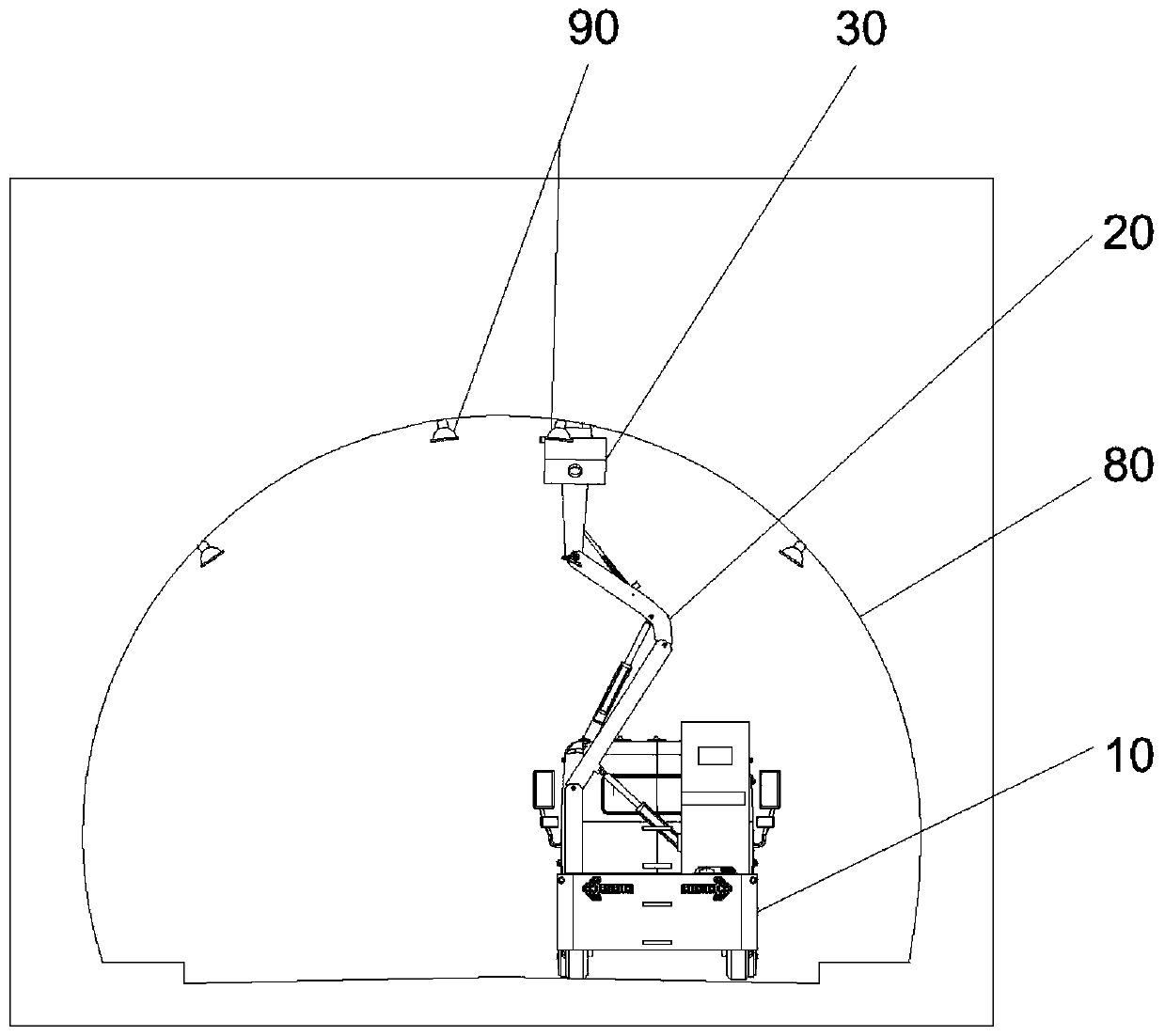
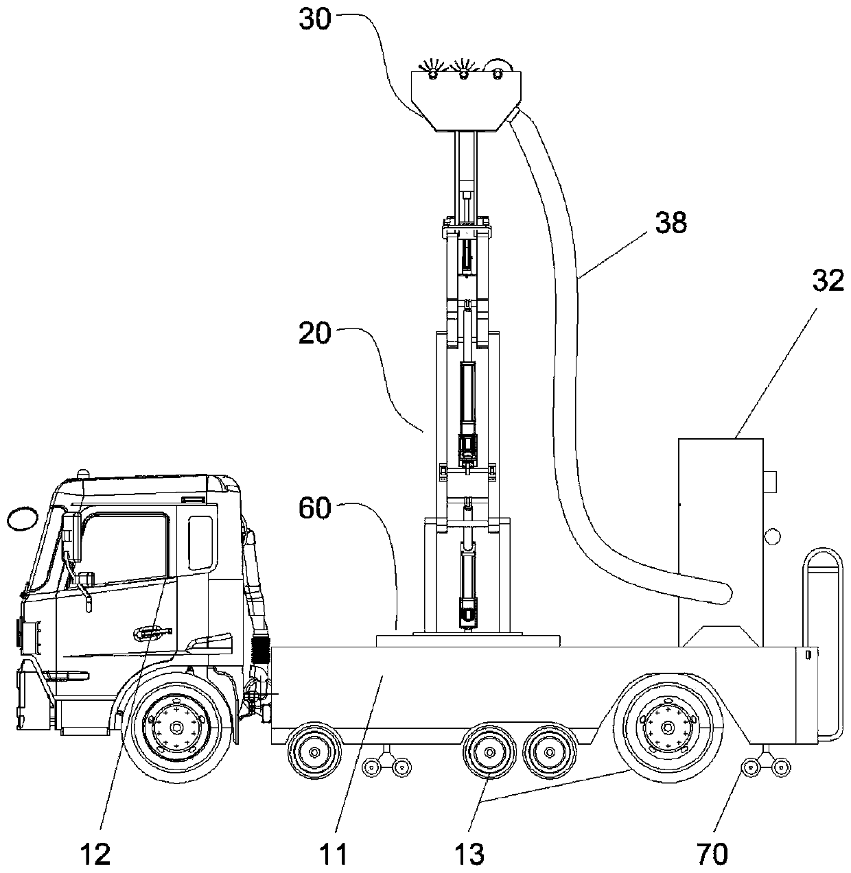
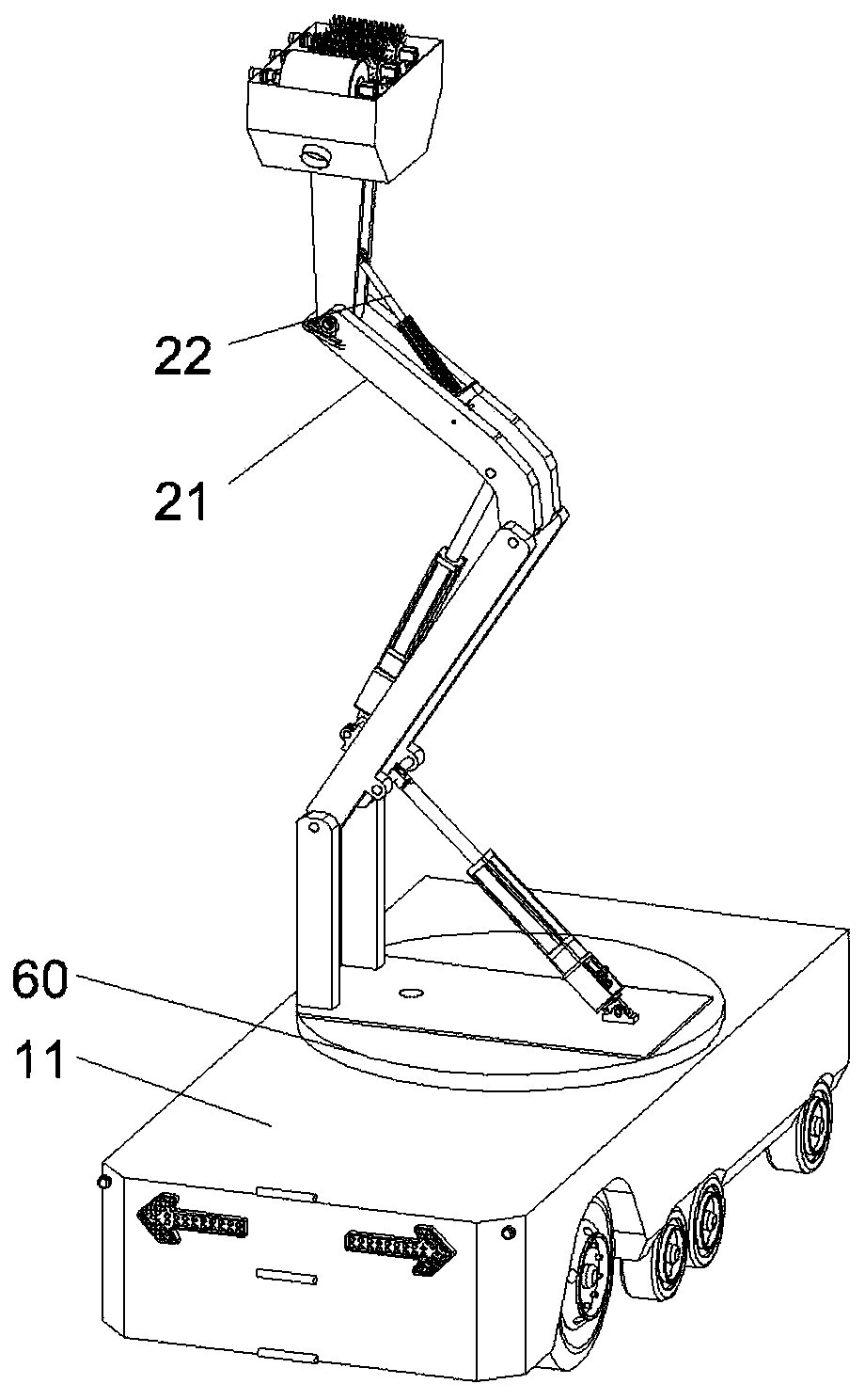
[0034] figure 1 It is a structural schematic diagram of the cleaning state of the present invention; figure 2 It is a schematic diagram of the overall structure of the present invention; image 3 It is a schematic diagram of the structure of the lifting platform; Figure 4 It is a schematic diagram of the structure of the cleaning device (with outer cover); Figure 5 It is a schematic diagram of the top view structure of the outer cover; Image 6 It is a schematic diagram of the sectional structure of the outer cover; Figure 7 It is a schematic diagram of the structure of the cleaning device (without the outer cover); Figure 8 Schematic diagram of the installation structure for the brush assembly; Figure 9 It is a structural schematic diagram of the brush assembly and the sponge roller; Figure 10 It is a schematic diagram of the switching structure of dual power sources;

[0035] As shown in the figure: the dual power source vehicle-mounted tunnel lamp cleaning sys...


PUM


Abstract

The invention discloses a dual-power-source vehicle-mounted tunnel lamp cleaning system. The dual-power-source vehicle-mounted tunnel lamp cleaning system comprises a vehicle-mounted platform, a lifting platform installed on the vehicle-mounted platform and a cleaning device installed on the lifting platform, the lifting platform is connected to the vehicle-mounted platform in ways of lifting and orientationchanging, the vehicle-mounted platform comprises two sets of power sources which are the high-speed power source andthe low-speed power source, and a switching device is arranged between the high-speed power source and the low-speed power source and used for switching the power sources to achieve normal running of the vehicle-mounted platform and low-speed running during lampcleaning. According to the cleaning system, the two sets of power sources are arranged, thus the normal running requirements of the vehicle-mounted platform can be met, and low-speed and stable runningduring lampscleaning can also be met.

Description

technical field [0001] The invention belongs to the technical field of lamp cleaning, and relates to a vehicle-mounted tunnel lamp cleaning system with dual power sources. Background technique [0002] Tunnel lighting is to solve the "black hole effect" or "white hole effect" caused by the sudden change of brightness when the vehicle enters or exits the tunnel. It is a special lamp used for tunnel lighting. The tunnel space is relatively sealed, so the exhaust gas and dust in the tunnel The content is high, and solid particles are easy to accumulate on the surface of the lampshade of the tunnel lamp, which affects the light transmittance of the lampshade, and then affects the lighting effect, resulting in insufficient light in the tunnel and affecting safe passage. Therefore, the lampshade of the tunnel lamp needs to be cleaned; [0003] At present, there are two main cleaning methods commonly used, namely wet cleaning and non-contact dry cleaning; among them, wet cleaning i...

Claims


Application Information

Patent Timeline
Patent Type & Authority Applications(China)
IPC IPC(8): E01H1/00E01H1/08
CPCE01H1/005
Inventor 罗斌王福敏丁浩张华李文锋陈建忠廖强马非须民健崔伟
Owner CHINA MERCHANTS CHONGQING COMM RES & DESIGN INST
Why Eureka
Try Eureka