
Rotating cathode of magnetron sputtering system

A technology of magnetron sputtering system and rotating cathode, which is applied in sputtering plating, ion implantation plating, metal material coating process, etc., can solve the problems of unstable structure and easy falling off.

Inactive Publication Date: 2019-09-24
镇江市德利克真空设备科技有限公司
View PDF0 Cites 0 Cited by
  • Summary
  • Abstract
  • Description
  • Claims
  • Application Information

AI Technical Summary

Problems solved by technology

But the existing structure is often not stable and easy to fall off

Method used


Image

  • Rotating cathode of magnetron sputtering system
  • Rotating cathode of magnetron sputtering system
  • Rotating cathode of magnetron sputtering system

Examples


Embodiment Construction

[0021] In order to deepen the understanding of the present invention, the present invention will be further described below in conjunction with the embodiments and accompanying drawings. The embodiments are only used to explain the present invention and do not constitute a limitation to the protection scope of the present invention.

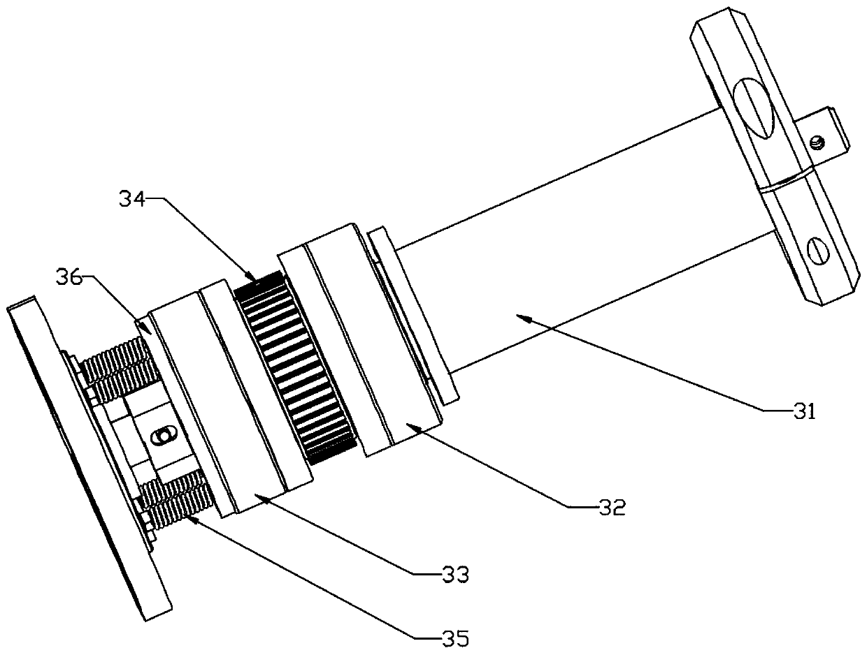
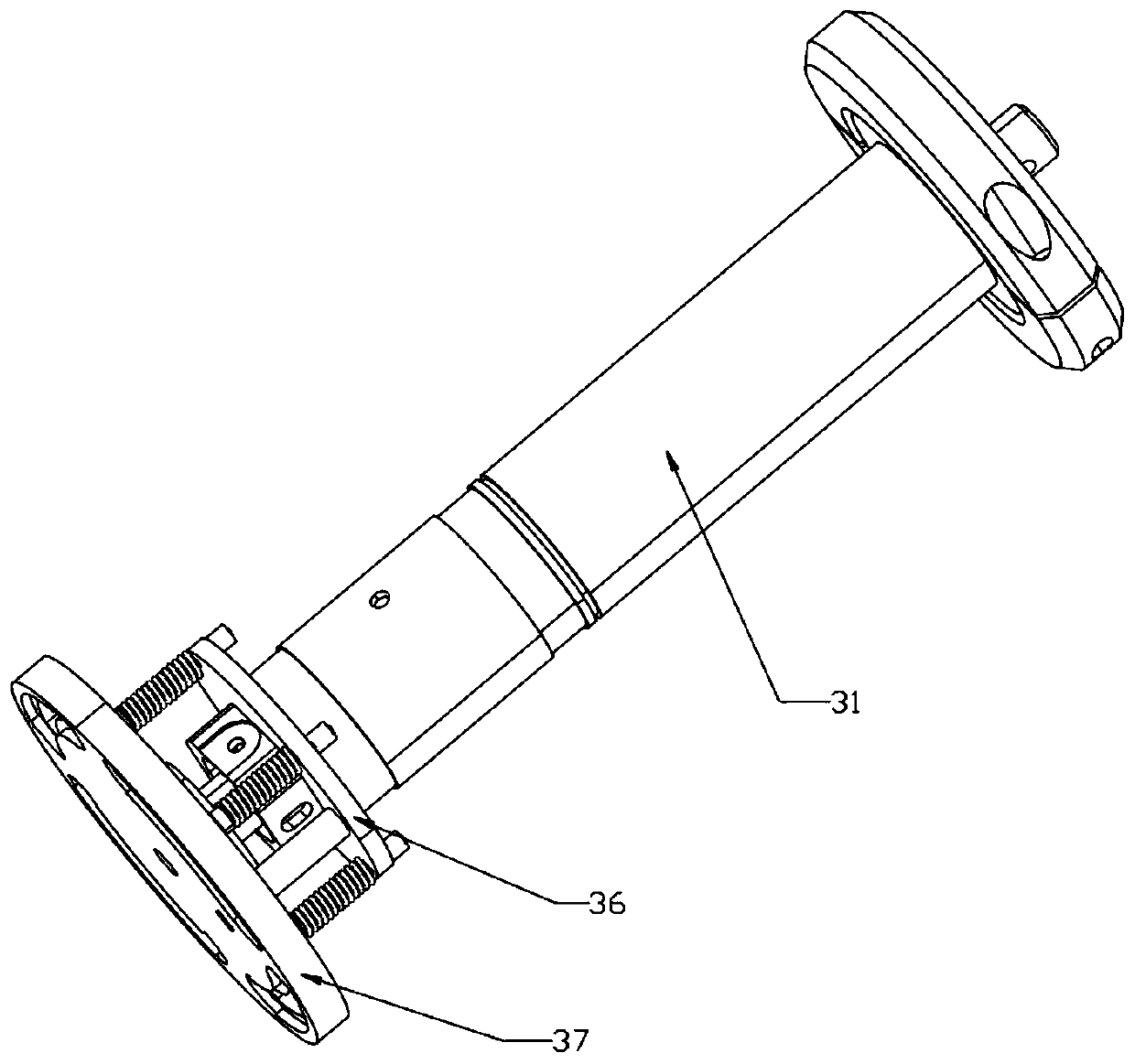
[0022] Such as Figure 1-7 As shown, a rotating cathode of a magnetron sputtering system includes a driving device 3 and a tubular target 1; the driving device 3 includes a main support tube 31, an outer sleeve 39 and a chassis 37; the main support tube 31 The upper frame seal 32, the upper connection bearing, the driven wheel 34, the lower connection bearing, the lower frame seal 33 and the flange-shaped copper conductor 36 are sleeved in sequence, and the copper conductor 36 passes through four uniformly distributed circumferential The support column is connected with the base frame 37, and the outer wall of the support column is provided with ...


PUM


Abstract

The invention discloses a rotating cathode of a magnetron sputtering system. The rotating cathode comprises a drive device and a tubular target; the drive device comprises a main supporting pipe, an outer sleeve and a chassis; the main supporting pipe is sequentially sleeved with an upper skeleton seal, an upper connecting bearing, a driven wheel, a lower connecting bearing, a lower skeleton seal and a flange-shaped copper conductor. By adopting four supporting columns evenly distributed at the circumference, the supporting columns are sleeved with compressing springs, the copper conductor is tightly attached to the lower skeleton seal through the four compressing springs, and therefore current transmission stability and reliability are ensured; compared with a traditional compressing mode, the device can supply more stable compressing force, and therefore the stability and reliability of the rotating cathode are ensured. After an experiment is performed for a certain period of time, and after the rotating cathode is in use for a long time, the phenomena that supporting is poor, vibration is caused and the binding face is not flush are avoided.

Description

technical field [0001] The invention relates to a rotating cathode of a magnetron sputtering system. Background technique [0002] Magnetron sputtering with rotating targets is widely used to form various thin films on substrates. In magnetron sputtering, the material to be sputtered is formed in a cylindrical shape or adhered to the outer surface of a cylindrical support tube made of rigid material. A magnetron assembly is housed within the tube and supplies magnetic flux, which passes through the target such that a substantial amount of magnetic flux exists on the outer surface of the target. [0003] The magnetic field is designed in such a way that the magnetic field retains the electrons emitted from the target, such as increasing the probability of ionized collisions of the electrons with the working gas, thereby enhancing the efficiency of the sputtering process. [0004] In order to ensure power supply when the rotating cathode is rotating, it is often necessary to...

Claims


Application Information

Patent Timeline
Patent Type & Authority Applications(China)
IPC IPC(8): C23C14/34C23C14/35
CPCC23C14/3407C23C14/35
Inventor 匡国庆
Owner 镇江市德利克真空设备科技有限公司
Learn More