
Glass pressing machine

A calender, glass technology, applied in glass calendering, glass forming, glass manufacturing equipment and other directions, can solve the problems of rolling, even wrapping, high surface temperature of rollers, rising production costs, etc. Uniform thickness and small thermal deformation

Pending Publication Date: 2019-09-24
XINYI PHOTOVOLTAIC IND (ANHUI) HLDG CO LTD
View PDF5 Cites 1 Cited by
  • Summary
  • Abstract
  • Description
  • Claims
  • Application Information

AI Technical Summary

Problems solved by technology

Due to the high temperature of the surface of the roller affected by the heat conduction of the high-temperature liquid material, if the water cooling inside the roller is not good, the thickness of the entire sheet will be uneven.
When the thickness deviation is serious, even because the thickness deviation of the plate cannot meet the national standard or industry standard, the plate cannot be normally picked and packed, resulting in a very low yield and a sharp increase in production costs
[0003] On the other hand, from the perspective of manufacturing process, when the high-temperature liquid material is pressed and formed by a calender with two main rollers, due to the high temperature of the material, especially in the field of glass ceramics, the temperature of the material before the rollers is generally above 1200 °C. If the pattern (pattern density, depth) engraved on the surface of the calender upper main roll is not suitable, the liquid material will be rolled up by the rotating calender upper main roll, or even wrapped on the calender upper main roll, causing damage to the glass calender equipment
For this reason, the glass calender with two main roller structures is greatly restricted in the production of required products (the types of patterns of products).

Method used


Image

  • Glass pressing machine
  • Glass pressing machine
  • Glass pressing machine

Examples


Embodiment 1

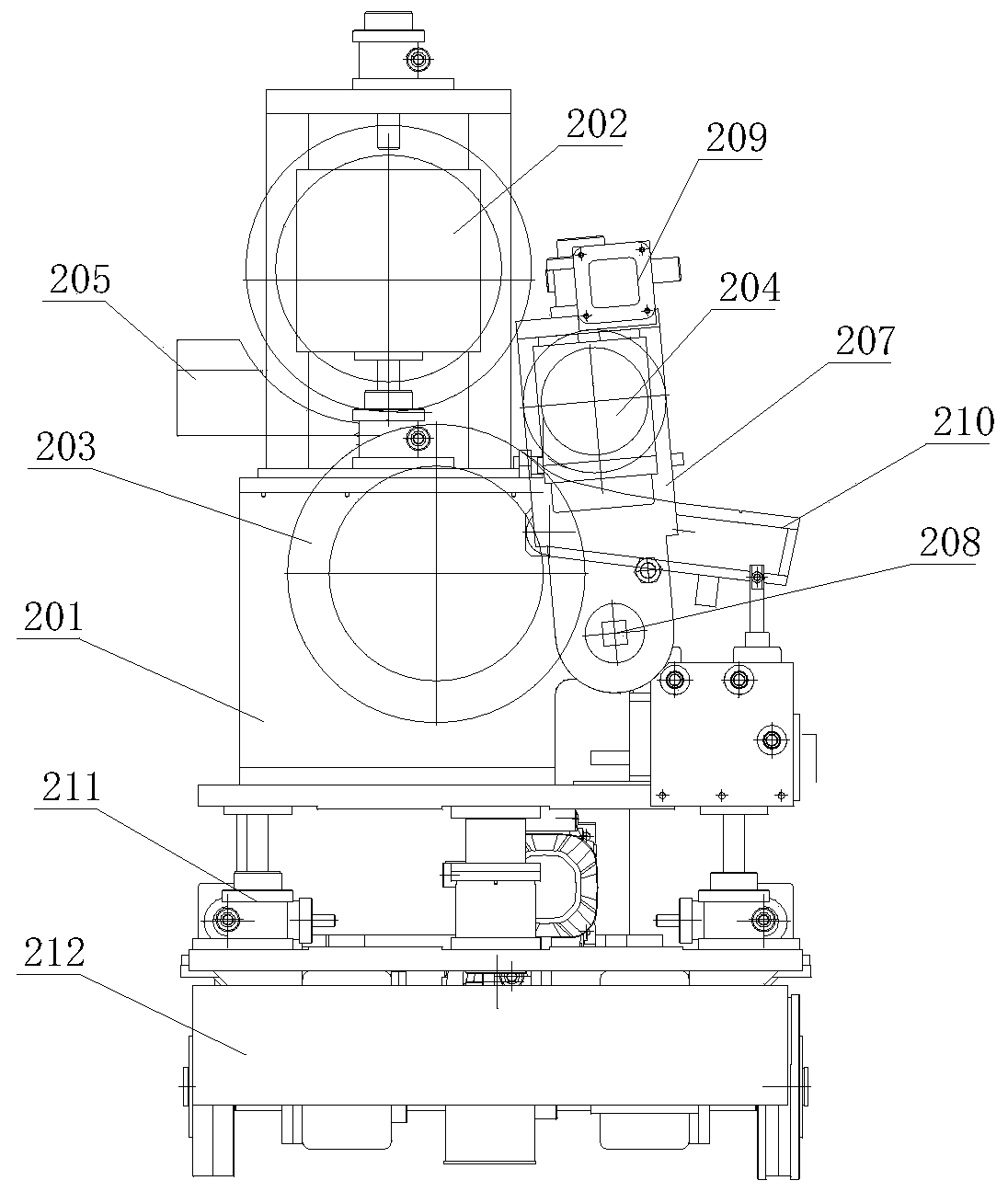
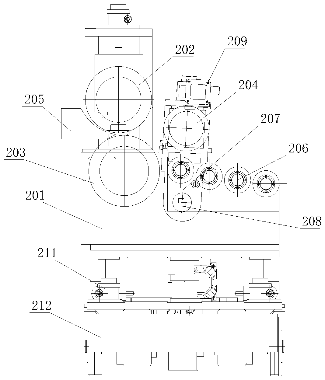
[0029] This embodiment provides a glass rolling machine, such as figure 2 , Figure 4 As shown, it includes base 201, upper main roller 202, lower main roller 203, secondary pressure roller 204, lip brick 205 and drag roller 206, upper main roller 202, lower main roller 203, secondary pressure roller 204 and drag roller 206 Both are installed on the top of the base 201, the upper main roller 202 is arranged on the top of the lower main roller 203, and the lip brick 205 is arranged on the head end of the upper main roller 202 and the lower main roller 203, for the upper main roller 202 and the lower main roller 203 The glass liquid is transported between them, and the lip brick 205 can be fixed directly on the top of the base 201, or can be installed on the kiln in front of the calender; the secondary pressure roller 204 and drag roller 206 are arranged on the upper main roller 202 and the lower main roller 203 at the tail end of the main roller 204, the secondary pressing ro...

Embodiment 2

[0035] Such as image 3 , Figure 5 As shown, the difference between this embodiment and Embodiment 1 is that, in this embodiment, no supporting plate water bag 210 is provided, and the secondary pressure roller 204 is arranged on the top of the drag roller 206, which is connected to the first end of the drag roller 206. The knuckle rollers are opposite and rotate in opposite directions. The specific working process is as follows:

[0036] Such as Figure 5 As shown, the liquid glass in the molten state is pressed into a certain thickness by the upper main roller 202 (driven by a separate frequency conversion motor, rotating in the V1 direction) and the lower main roller 203 (driven by a separate frequency conversion motor, rotating in the V2 direction) of the calender. The glass is pressed into a plate of final thickness by the secondary pressing roller 204. The plate passes through the drag roller 206 (rotated by a separate frequency conversion motor), and then passes thr...


PUM


Abstract

The invention discloses a glass pressing machine. The glass pressing machine comprises a base, an upper main roller, a lower main roller, a secondary pressing roller, a lip tile and pulling rollers. The upper main roller, the lower main roller, the secondary pressing roller and the pulling rollers are installed at the top of the base, the upper main roller is arranged at the top of the lower main roller, and the lip tile is arranged at the head ends of the upper main roller and the lower main roller and used for conveying glass liquid to the portion between the upper main roller and the lower main roller; the secondary pressing roller is arranged at the tail end of the upper main roller, the pulling rollers are arranged at the tail end of the lower main roller, the secondary pressing roller is used for conducting secondary pressing on glass pressed by the upper main roller and the lower main roller, and the pulling rollers convey the pressed glass to other processes. The provided glass pressing machine has a secondary pressing function, the thickness of a liquid glass material pressed by the glass pressing machine is more uniform, products with various flower types can be obtained through pressing, and the roller wrapping phenomenon cannot occur.

Description

technical field [0001] The invention relates to the technical field of glass manufacturing, in particular to a glass rolling machine. Background technique [0002] At present, the main structure of the calender used for glass production is composed of two main rollers (calendering upper main roller 101, calendering lower main roller 102), a supporting plate water bag 103 for receiving glass or a transmission roller 104 behind which drives the glass forward. (Such as figure 1 shown). The two main rollers pass water inside, and its function is to quickly press the glass liquid above 1000 degrees into a plate with a certain thickness and pattern. After being pressed by two main rollers, the temperature of the plate drops rapidly to between 620°C and 880°C. The water cooling inside the two main rollers is very critical. On the one hand, it can quickly cool down the glass liquid, and on the other hand, it can strictly control the thickness deviation of the plate. Due to the h...

Claims


Application Information

Patent Timeline
Patent Type & Authority Applications(China)
IPC IPC(8): C03B13/00C03B13/16
CPCC03B13/00C03B13/16
Inventor 单晓义
Owner XINYI PHOTOVOLTAIC IND (ANHUI) HLDG CO LTD
Learn More