Intelligent visual doorbell awakening method

A doorbell, intelligent technology, applied in the direction of TV, CCTV system, electrical components, etc., can solve the problems of detector false alarm, high false alarm rate, popularization of video doorbell and installation site obstruction, etc., to achieve the effect of improving standby time

Inactive Publication Date: 2019-09-20
SHENZHEN ELINK SMART CO LTD
View PDF6 Cites 1 Cited by
  • Summary
  • Abstract
  • Description
  • Claims
  • Application Information

AI Technical Summary

Problems solved by technology

The detection wavelength range of the infrared sensor is 8-14μm. Since the infrared radiation wavelength of the human body is just within this detection wavelength range, it can better detect the moving human body. The passive alarm detector has good detection performance, easy deployment, and low price. Cheap and widely used, its disadvantage is that compared with active detection, the false positive rate is higher, and the induction effect of passive infrared detector is closely related to the change of temperature
[0005] Both hot and cold vents and cold and heat sources may cause false alarms of the detector. For some low-performance detectors, sometimes air convection through doors and windows will also cause false alarms. Objects that are easy to swing will make the microwave detector work. , so it is also possible to cause false alarms. Sunlight should contain light of all wavelengths, so when the PIR detector is facing the sun, the false alarm rate is very high
[0006] In recent years, with the development of network technology, wireless smart video doorbells with remote video and intercom have become more and more widely used. As one of the main wake-up methods, PIR has become an indispensable component in the smart video doorbell industry, but The false alarm of PIR has brought great obstacles to the popularization and installation location of video doorbell, especially the false alarm of PIR due to sunlight has brought great limitations to the installation of smart video doorbell

Method used


Image

  • Intelligent visual doorbell awakening method

Examples


Embodiment Construction

[0020] In order to make the object, technical solution and advantages of the present invention clearer, the present invention will be further described in detail below in conjunction with the accompanying drawings and embodiments. It should be understood that the specific embodiments described here are only used to explain the present invention, not to limit the present invention.

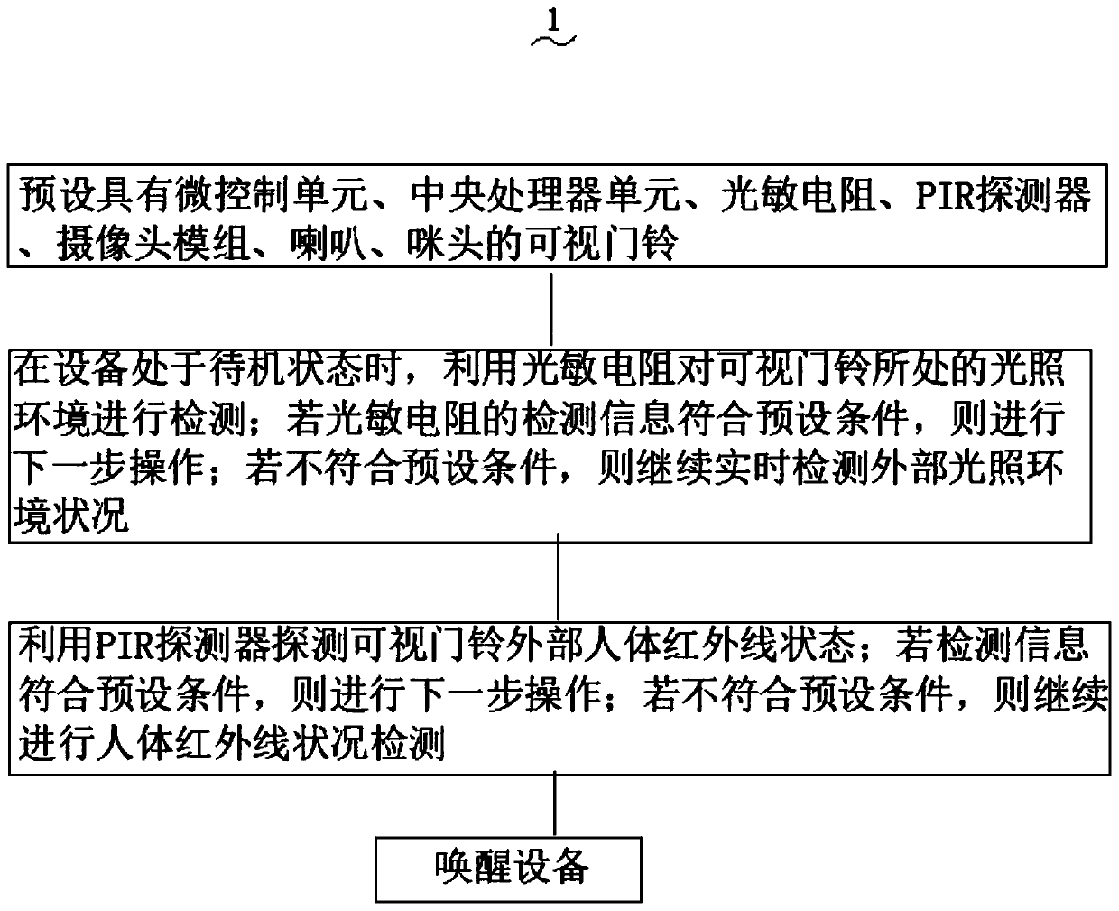
[0021] see figure 1 A wake-up method 1 of an intelligent video doorbell of the present invention comprises the following steps,

[0022] S1: preset video doorbell with micro control unit, central processing unit, photoresistor, PIR detector, camera module, speaker and microphone;

[0023] S2: When the device is in the standby state, use the photoresistor to detect the light environment where the video doorbell is located; if the detection information of the photoresistor meets the preset conditions, proceed to the next step; if not meet the preset conditions, continue Real-time detection of exter...


PUM


Abstract

The invention provides an intelligent visual doorbell awakening method which comprises the following steps: S1, presetting a visual doorbell with a micro-control unit, a central processing unit, a photoresistor, a PIR detector, a camera module, a loudspeaker and a microphone; s2, when the equipment is in a standby state, detecting the illumination environment where the visual doorbell is located by using a photoresistor; if the detection information of the photoresistor meets the preset condition, performing the next step of operation; if the detection information of the photoresistor does not meet the preset condition, continuously detecting the external illumination environment condition in real time. According to the method, before whether the PIR signal exists or not is detected, the environment where the visual doorbell is located, namely the light intensity, is detected firstly, the visual doorbell can be prevented from being mistakenly awakened due to the fact that the visual doorbell is irradiated by sunlight to a great extent, and therefore the standby time of a product can be greatly prolonged.

Description

[0001] [technical field] [0002] The invention relates to the technical field of doorbell wake-up methods, in particular to an intelligent video doorbell wake-up method that can largely prevent the visual doorbell from being erroneously awakened by sunlight and greatly improve the standby time of the product. [0003] [Background technique] [0004] PIR is the abbreviation of Passive Infra Red, which is passive infrared technology. The full name of PIR detector is Passive Infrared Detection (passive infrared detection, sometimes called Passive Infrared Sensor, and detectors in the security industry are often called Detection). The detection wavelength range of the infrared sensor is 8-14μm. Since the infrared radiation wavelength of the human body is just within this detection wavelength range, it can better detect the moving human body. The passive alarm detector has good detection performance, easy deployment, and low price. It is cheap and widely used, but its disadvantage ...

Claims


Application Information

Patent Timeline
IPC IPC(8): H04N7/18
CPCH04N7/186
Inventor 张江柯浩伟
Owner SHENZHEN ELINK SMART CO LTD
Why Eureka
Try Eureka