A motor and its motor shaft

A technology of motor shaft and motor body, applied in electromechanical devices, electrical components, electric components, etc., can solve problems such as affecting the service life of the motor, inconvenient shutdown of the servo motor speed, and rising internal temperature of the motor.

Active Publication Date: 2021-04-09
无锡港大电机有限公司
View PDF7 Cites 0 Cited by
  • Summary
  • Abstract
  • Description
  • Claims
  • Application Information

AI Technical Summary

Problems solved by technology

[0003] However, when the temperature of the existing servo motor rises, it is necessary to stop the motor to dissipate heat. If the speed of the servo motor is too fast, it is inconvenient to stop it. If the speed of the motor is high, the internal temperature of the motor will rise, which will affect the service life of the motor.

Method used


Image

  • A motor and its motor shaft
  • A motor and its motor shaft
  • A motor and its motor shaft

Examples


Embodiment Construction

[0025] In order to make the technical means, creative features, goals and effects achieved by the present invention easy to understand, the present invention will be further described below in conjunction with specific embodiments.

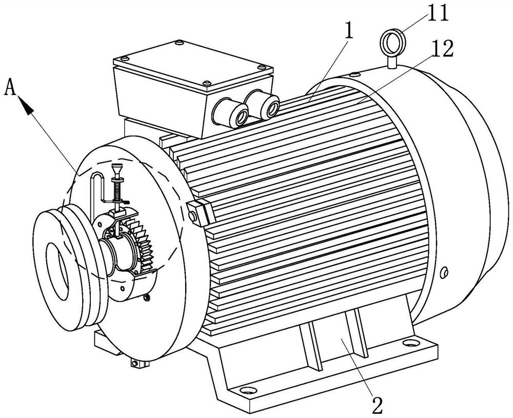
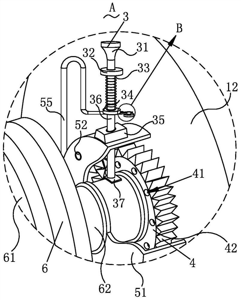
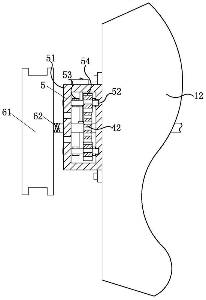
[0026] Such as Figure 1-Figure 6 As shown, a kind of electric machine described in the present invention comprises a starting mechanism 1, a base 2, a limit mechanism 3, a linkage mechanism 4, a cooling mechanism 5, a driving mechanism 6 and a pushing mechanism 7; One end of 1 is rotationally connected with the driving mechanism 6, and the side wall of the driving mechanism 1 is installed with the heat dissipation mechanism 5 which is rotationally connected with the driving mechanism 6, and the driving mechanism 5 located inside the heat dissipation mechanism 5 The linkage mechanism 4 engaged with the heat dissipation mechanism 5 is installed inside the mechanism 6, and the limit mechanism 3 for decelerating the driving mechanism 6 is installed o...


PUM


Abstract

The invention relates to the field of motors, specifically a motor and its motor shaft, including an engine mechanism, a base, a limit mechanism, a linkage mechanism, a heat dissipation mechanism, a drive mechanism and a push mechanism; One end of the motor body communicates with the air bag on the side wall of the motor body. When the speed of the motor body is too fast and needs to be decelerated, the airflow generated by the fan blade is transported from the air pipe to the inside of the air bag, further realizing The expansion of the airbag pushes the push plate, so that the pulling pin is separated from the disc, and finally the return spring expands the pressing rod to move to the inside of the protective shell, further realizing the The brake pads collide with the motor shaft to brake, decelerate, and protect the motor body. After the motor body drives the motor shaft to rotate, it drives the drive sprocket to rotate. When the pulley drives the equipment that needs to be driven to rotate, the drive sprocket drives The heat dissipation mechanism dissipates heat for the motor shaft.

Description

technical field [0001] The invention relates to the field of motors, in particular to a motor and a motor shaft thereof. Background technique [0002] The motor is represented by the letter M (the old standard is D) in the circuit. Its main function is to generate driving torque as a power source for electrical appliances or various machines. The generator is represented by the letter G in the circuit. Its main function The function is to convert mechanical energy into electrical energy. The working principle of a DC generator is to convert the alternating electromotive force induced in the armature coil to a DC electromotive force when it is drawn out from the brush end by the commutator and the commutation effect of the brush. principle. [0003] However, when the temperature of the existing servo motor rises, it is necessary to stop the motor to dissipate heat. If the speed of the servo motor is too fast, it is inconvenient to stop the motor. If the speed of the motor is...

Claims


Application Information

Patent Timeline
Patent Type & Authority Patents(China)
IPC IPC(8): H02K9/06H02K5/20H02K7/102H02K7/00
CPCH02K5/20H02K7/003H02K7/102H02K9/06
Inventor 陈江陈路阳朋仁锋凡得雨
Owner 无锡港大电机有限公司
Why Eureka
Try Eureka