Unloading frame for logistics cargo transport

A technology of cargo transportation and logistics, which is applied in the directions of transportation and packaging, loading/unloading, roller tables, etc., which can solve the problems of providing buffers for goods, failing to meet the needs of use, and poor unloading effects. It achieves simple structure, good unloading effect, Ease of use

Inactive Publication Date: 2020-09-18
岳阳泓发科技服务有限公司
View PDF11 Cites 0 Cited by
  • Summary
  • Abstract
  • Description
  • Claims
  • Application Information

AI Technical Summary

Problems solved by technology

[0003] At present, after the logistics vehicle transports the goods to the destination, it needs to use the unloading rack to unload the goods from the logistics vehicle. When the existing unloading rack unloads the goods, it cannot provide a buffer for the goods and needs to be unloaded manually. The bottom of the rack is connected to the goods, so that the existing unloading rack has the defect of poor unloading effect and cannot meet the needs of use

Method used


Image

  • Unloading frame for logistics cargo transport
  • Unloading frame for logistics cargo transport
  • Unloading frame for logistics cargo transport

Examples


Embodiment 1

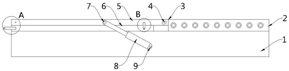
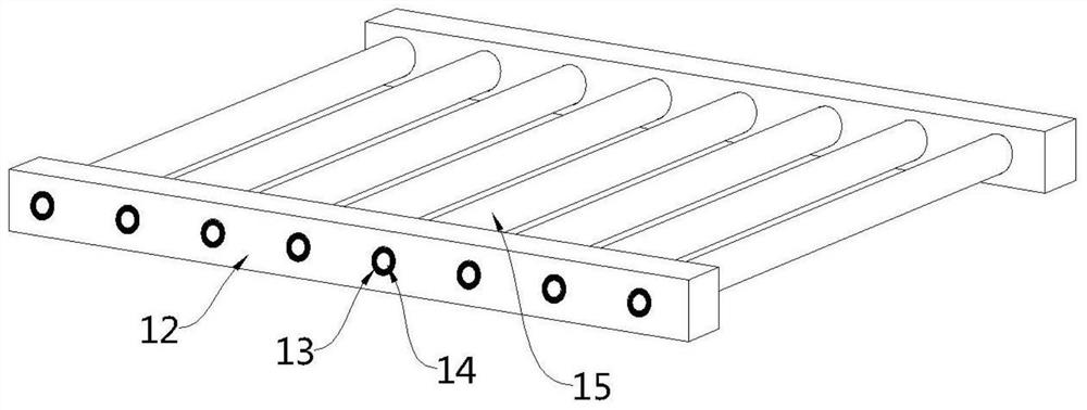
[0026] see Figure 1-3 , this embodiment provides an unloading rack for logistics cargo transportation, including a base 1, a deceleration assembly 2 is provided on one side of the upper part of the base 1, and a first unloading assembly 5 is provided on the other side, and the first unloading assembly 5 is provided The assembly 5 is rotatably connected to one side of the deceleration assembly 2, and the front and rear sides of the base 1 are symmetrically provided with a power assembly 8 for driving the first unloading assembly 5 to rotate upwards. Specifically, the deceleration assembly includes 2 Two sets of second support side plates 12 fixedly arranged on the upper part of the base 1, the two sets of second support side plates 12 are oppositely arranged, and a number of equal intervals are arranged between the two sets of second support side plates 12 along the length direction. The second roller shaft 15, the two ends of each group of the second roller shaft 15 are rotat...

Embodiment 2

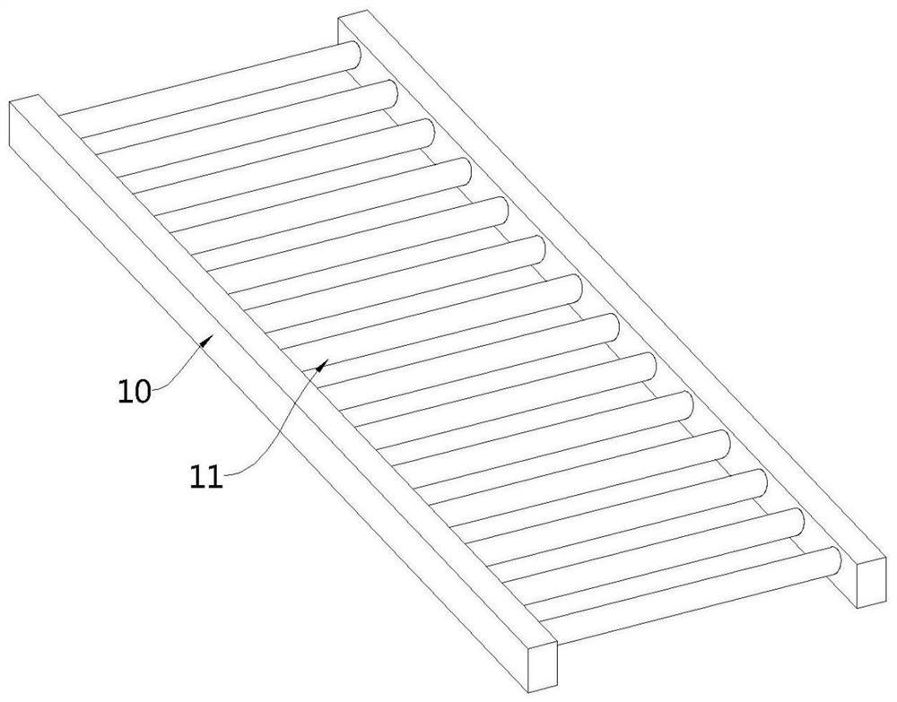
[0036] see Figure 4-5 , an unloading rack for logistics cargo transportation. Compared with Embodiment 1, the side wall of the end of the first supporting side plate 10 corresponding to the second unloading assembly 6 in this embodiment is fixedly provided with a first fixing rod 16, so One end of the first fixing rod 16 extends to the side of the first supporting side plate 10, and the first fixing rod 16 is provided with a first through hole 17, and the corresponding first supporting side plate 10 side of the first unloading assembly 5 The wall defines a first concave hole 18 corresponding to the first through hole 17 .

[0037] When the second unloading assembly 6 is extended to one end of the first unloading assembly 5, the first fixing rod 16 extends to the side of the first supporting side plate 10 corresponding to the first unloading assembly 5, and the first through hole 17 and The positions of the first concave holes 18 are aligned, and a pin is inserted from the fi...


PUM


Abstract

The invention provides an unloading frame for logistics cargo transport, and belongs to the technical field of logistics unloading. The unloading frame comprises a base, a speed reduction assembly isarranged on one side of the upper portion of the base, a first unloading assembly is arranged on the other side, the first unloading assembly is rotatably connected to one side of the speed reductionassembly, power assemblies used for driving the first unloading assembly to rotate upwards are arranged on the front side and the back side of the base symmetrically, the unloading frame has the advantages of being simple in structure, convenient to use and good in unloading effect, cargos are unloaded to second roller shafts corresponding to the speed reduction assembly through the first unloading assembly and can slide along the upper portions of the second roller shafts, when the cargos slide on the upper portions of the second roller shafts, the second roller shafts are driven to rotate, under the effect of a damping ring, rotation of the second roller shafts has certain resistance, speed reduction of the cargos is achieved, and it is ensured that the cargos can be stably stopped on the upper portion of a certain set of second roller shafts.

Description

technical field [0001] The invention belongs to the technical field of logistics unloading, in particular to an unloading rack for logistics cargo transportation. Background technique [0002] The unloading rack is a tool used to unload the goods. When unloading the logistics goods, the unloading rack for logistics goods transportation is needed. [0003] At present, after the logistics vehicle transports the goods to the destination, it needs to use the unloading rack to unload the goods from the logistics vehicle. When the existing unloading rack unloads the goods, it cannot provide a buffer for the goods and needs to be unloaded manually. The bottom of the rack is connected to the goods, so that the existing unloading rack has the defect of poor unloading effect and cannot meet the needs of use. Contents of the invention [0004] In view of the above-mentioned deficiencies in the prior art, the technical problem to be solved by the embodiments of the present invention ...

Claims


Application Information

Patent Timeline
Patent Type & Authority Applications(China)
IPC IPC(8): B65G67/24B65G13/00
CPCB65G67/24B65G13/00
Inventor 万政一
Owner 岳阳泓发科技服务有限公司
Why Eureka
Try Eureka