
High-pressure phosphorous removal auxiliary device

An auxiliary device and high-pressure technology, which is applied in the direction of cleaning methods and tools, grinding machines, grinding/polishing equipment, etc., can solve the problems of high output energy consumption, affecting production, and fast accumulation of waste sand layers, so as to prevent leakage vibration, The effect of vibration effect enhancement

Active Publication Date: 2019-09-20
GUANGZHOU SITIAN AUTOMOBILE SUPPLIES CO LTD
View PDF9 Cites 1 Cited by
  • Summary
  • Abstract
  • Description
  • Claims
  • Application Information

AI Technical Summary

Problems solved by technology

At present, domestic enterprises generally use chemical pickling methods (such as: hydrochloric acid, sulfuric acid, nitric acid, hydrofluoric acid) to remove the scale on the outer surface of the steel strip, which seriously pollutes the environment; descaling by shot blasting can partially remove the scale on the outer surface of the steel strip , but the dust pollution is serious, it is generally equipped with dust removal equipment, and it is difficult to meet the process requirements, and it is easy to cause pits on the surface of the steel strip
[0003] According to the above problems, after retrieval: Chinese Patent No.: CN201610054044.1 discloses a multi-channel sandblasting dephosphorization process. mouth, so a large amount of corundum supply is required. From the perspective of long-term operation, its output energy consumption (corundum) is too large, which will increase the production cost of the enterprise; and due to the excessive number of nozzles, the accumulation speed of the waste sand layer under the steel belt Fast, requires frequent manual shutdown processing, which will affect the output

Method used


Image

  • High-pressure phosphorous removal auxiliary device
  • High-pressure phosphorous removal auxiliary device
  • High-pressure phosphorous removal auxiliary device

Examples


Embodiment Construction

[0039] Below in conjunction with accompanying drawing and embodiment of description, specific embodiment of the present invention is described in further detail:

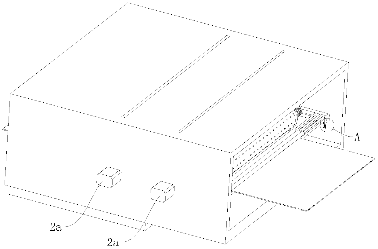
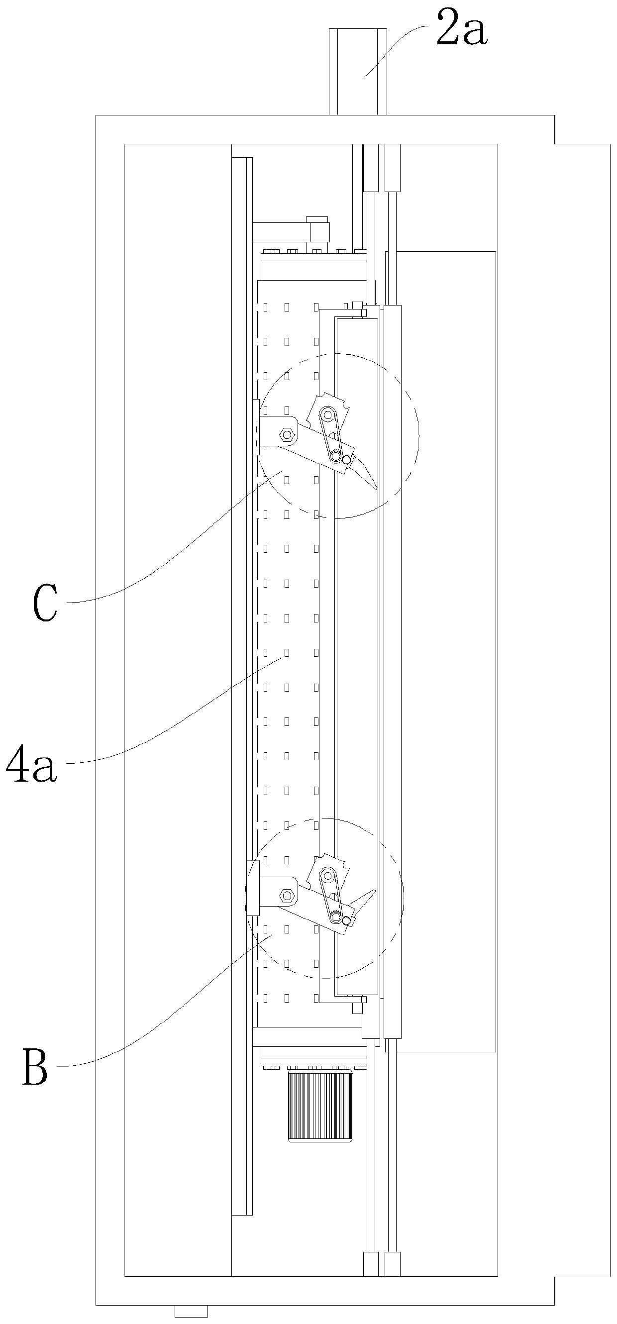
[0040] refer to Figure 1 to Figure 12 The high-pressure dephosphorization auxiliary device shown includes a dephosphorization bin, which is equipped with vibrating rollers and high-pressure rejectors close to its left and right ends respectively. There are two or more sets of pinch rollers on both sides of each vibrating roller, and between the two adjacent pinch roll sets and next to the pinch roll set closest to the outlet of the dephosphorization bin There is a grinding and washing roller 2 on each side, and the vibrating roller includes an upper beam frame 3, a transfer cylinder 4, a planetary hollow roller 5 and a frequency conversion motor 5b. The end is suspended downwards, the transmission cylinder 4 is horizontally hinged in the free end of the upper beam frame 3, the planetary hollow roller 5 is pivotall...


PUM


Abstract

The invention relates to the field of steel belt phosphorous removal equipment, in particular to a high-pressure phosphorous removal auxiliary device which comprises a phosphorous removing bin. Two vibrating rollers and two high-pressure removing devices close to the left end and the right end of the phosphorous removing bin are arranged in the phosphorous removing bin. Pressing roller sets are arranged on the two sides of each vibrating roller correspondingly. Abrasive cleaning rollers are arranged between two close pressing roller sets, and beside one pressing roller set close to the outlet end of the phosphorous removing bin. Each vibrating roller comprises an upper beam frame, a transferring cylinder, a planetary hollow roller and a variable frequency motor, wherein the top end of the upper beam frame is connected to the upper portion in the phosphorous removing bin in a shaft manner, the transferring cylinder is horizontally hinged into the free end of the upper beam frame, the planetary hollow roller is connected into the transferring cylinder in a shaft manner, at least one third portion of the outer side face of the planetary hollow roller is matched with the inner wall of the transferring cylinder in a friction manner, the variable frequency motor is arranged outside the transferring cylinder and connected with the planetary hollow roller in a transmission manner, and one supporting beam plate is arranged below each transferring cylinder. The high-pressure phosphorous removal auxiliary device can reduce the use cost of steel belt phosphorous removal substantially.

Description

technical field [0001] The invention relates to the field of steel strip dephosphorization equipment, in particular to a high-pressure dephosphorization auxiliary device. Background technique [0002] Oxide skin will be produced on the outer surface of the steel strip, and the oxide scale on the surface of the steel strip must be cleaned before processing. At present, domestic enterprises generally use chemical pickling methods (such as: hydrochloric acid, sulfuric acid, nitric acid, hydrofluoric acid) to remove the scale on the outer surface of the steel strip, which seriously pollutes the environment; descaling by shot blasting can partially remove the scale on the outer surface of the steel strip , but the dust pollution is serious, generally equipped with dust removal equipment, and it is difficult to meet the process requirements, and it is easy to cause pits on the surface of the steel strip. [0003] According to the above problems, after retrieval: Chinese Patent No...

Claims


Application Information

Patent Timeline
IPC IPC(8): B24B27/033B24C1/08B08B7/02B08B3/02
CPCB08B3/02B08B7/02B24B27/033B24C1/086Y02P70/10
Inventor 施荣建
Owner GUANGZHOU SITIAN AUTOMOBILE SUPPLIES CO LTD
Learn More