
Riveting tooling mold for metal sheet metal parts

A technology for riveting tooling and metal plates, applied in the field of plate processing, can solve the problems of reduced riveting precision, high work cost, large working space, etc., and achieve the effects of preventing the reduction of riveting precision, high adjustability and improving riveting precision

Active Publication Date: 2020-08-28
江苏宝祥电力设备有限公司
View PDF5 Cites 0 Cited by
  • Summary
  • Abstract
  • Description
  • Claims
  • Application Information

AI Technical Summary

Problems solved by technology

[0004] (1) The size of the existing riveting tooling molds is mostly fixed, that is, one tooling mold can only be used for one or a few sizes of rivets, so in order to meet different work needs, it is necessary to prepare a variety of tooling molds, which takes up a lot of work The space is larger, and the work cost is also higher;
[0005] (2) The installation position of the existing riveting tooling mold is fixed. When processing different positions of the sheet metal parts, the sheet metal parts need to be moved and re-fixed. Under a series of manual operation steps, it is easy to accumulate large errors , resulting in reduced riveting accuracy

Method used


Image

  • Riveting tooling mold for metal sheet metal parts
  • Riveting tooling mold for metal sheet metal parts
  • Riveting tooling mold for metal sheet metal parts

Examples


Embodiment Construction

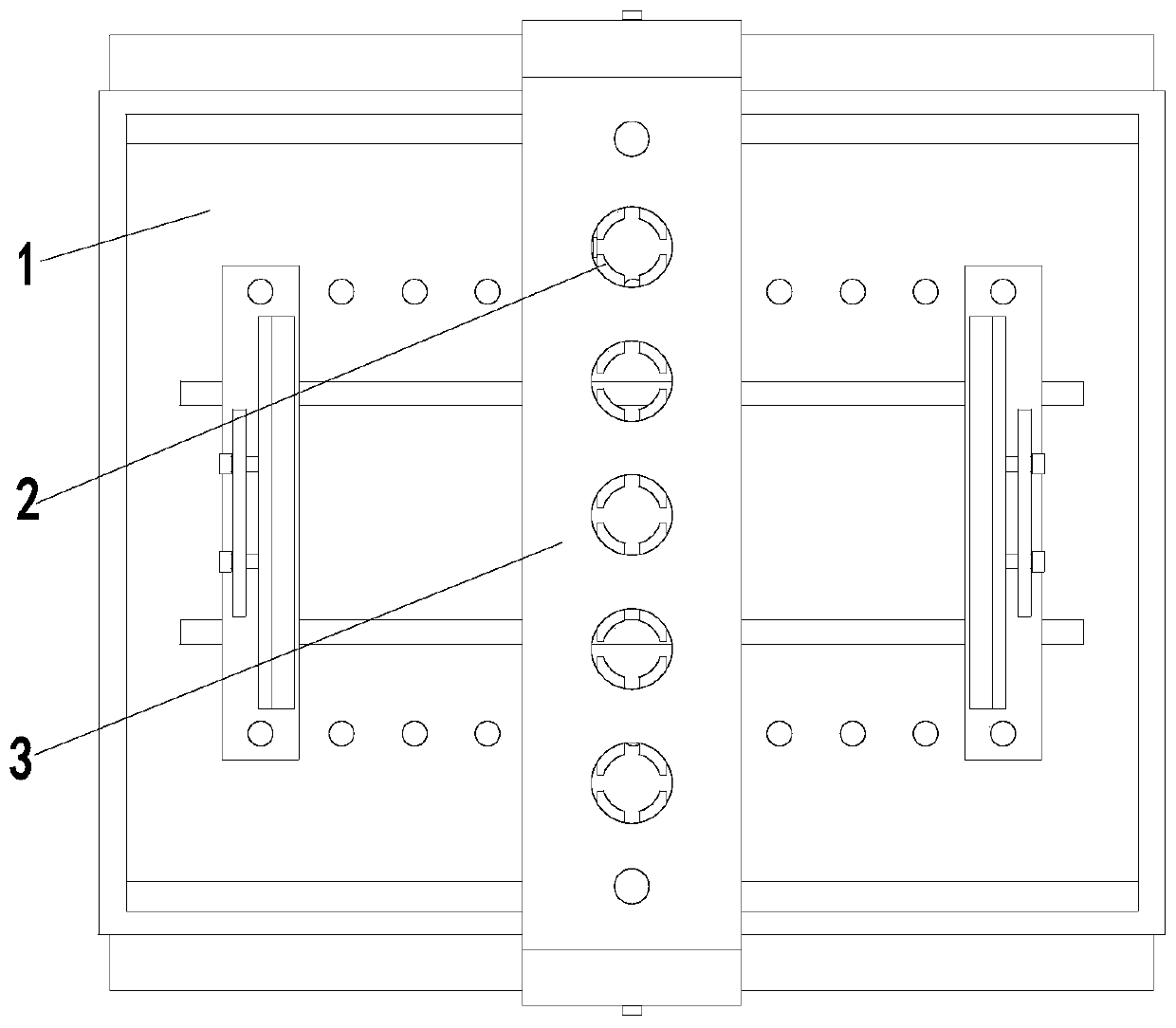
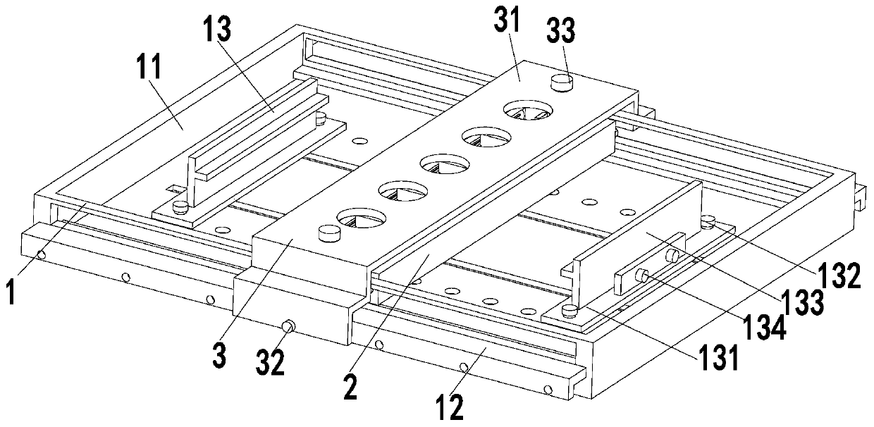
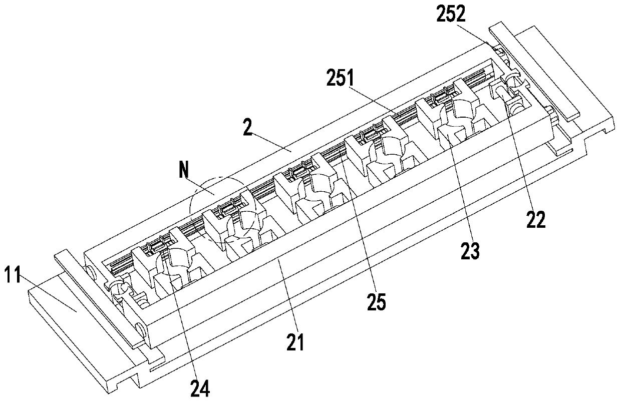
[0029] In order to make the technical means realized by the present invention, creative features, goals and effects easy to understand, the following combination Figure 1 to Figure 5 , to further elaborate the present invention.

[0030] A riveting tooling mold for metal sheet metal parts, including a fixed frame 1, a supporting mold 2 and a guiding mold 3, a supporting mold 2 is installed in the fixed frame 1, and a guiding mold is arranged on the upper end of the supporting mold 2 3. The guide mold 3 is installed on the outer wall of the fixed frame 1; where:

[0031] The fixed frame 1 includes a frame body 11, a positioning plate 12 and a clamping branch chain 13. The front and rear sides of the frame body 11 are symmetrically provided with strip grooves, and a positioning plate 12 is installed at the lower end of the strip groove. The positioning plate 12 is an inverted L shape. structure, positioning holes are evenly opened from left to right on the side wall of the pos...


PUM


Abstract

The invention relates to a metal sheet material sheet metal part riveting tooling mold. The metal sheet material sheet metal part riveting tooling mold comprises a fixed frame, bearing supporting molds and a position guide mold, wherein the fixed frame is internally provided with the bearing supporting molds, the upper ends of the bearing supporting molds are provided with the position guide mold, the position guide mold is installed on the outer wall of the fixed frame, the fixed frame comprises a frame body, positioning plates and clamping branch chains, the bearing supporting molds comprise a bearing supporting rack, adjusting bolts, adjusting blocks, adjusting rods and rotating rods, the position guide mold comprises a position guide rack, a positioning rod and a connection rod, and each clamping branch chain comprises a sliding rack, butt joint rods, a clamping plate and fastening bolts. According to the metal sheet material sheet metal part riveting tooling mold, by means of mutual coordination between the bearing supporting molds of adjustable gaps and the position guide mold capable of moving left and right, the riveting work of sheet metal parts is assisted, the purpose of improving the riveting accuracy is achieved, and the metal sheet material sheet metal part riveting tooling mold is suitable for rivets of different sizes and can meet the work requirements for single-row riveting and multi-row riveting.

Description

technical field [0001] The invention relates to the field of plate processing, in particular to a riveting tooling die for metal plate-like sheet metal parts. Background technique [0002] Sheet metal is a comprehensive cold working process for thin metal plates, including shearing, punching / cutting / compositing, folding, welding, riveting, splicing, forming, etc. Its notable feature is that the thickness of the same part is the same, and processed by sheet metal technology The product is called a sheet metal part. [0003] Riveting, that is, rivet connection, is a method of using axial force to thicken the nail rod in the rivet hole of the part and form a nail head to connect multiple parts. When riveting sheet metal parts, in order to ensure the accuracy of the riveting position and the verticality of the rivet installation, riveting tooling molds are often used for assistance. In actual work, there are the following problems: [0004] (1) The size of the existing riveti...

Claims


Application Information

Patent Timeline
Patent Type & Authority Patents(China)
IPC IPC(8): B21J15/30B21J15/32B21J15/38
CPCB21J15/30B21J15/32B21J15/38
Inventor 崔路飞李成
Owner 江苏宝祥电力设备有限公司
Learn More