Circularly polarized antenna device with high isolation

A circularly polarized antenna, high isolation technology, applied to antenna grounding devices, devices that enable antennas to work in different bands at the same time, antennas, etc., can solve problems such as unsatisfactory applications, increased antenna size, and insufficient beam width. Achieve the effects of easy processing design and assembly, increased working bandwidth, and stable phase center

Pending Publication Date: 2019-09-17
江苏三和欣创通信科技有限公司
View PDF0 Cites 1 Cited by
  • Summary
  • Abstract
  • Description
  • Claims
  • Application Information

AI Technical Summary

Problems solved by technology

[0009] 1. Ordinary microstrip antennas generally implement a single-layer medium to achieve a working frequency band. This kind of working bandwidth is relatively narrow, and the working bandwidth is only about 5%. It cannot be well applied in ultra-wideband (spread spectrum) communication systems.
If the bandwidth is increased, it is often necessary to use a medium with a low dielectric constant as the antenna substrate material, and the antenna size will increase at this time
[0010] 2. Conventional helical antennas have good frequency bandwidth, beam width, symmetric pattern, and wide-angle circular polarization. The disadvantage is that only one polarization mode can be realized.
In the case where dual circular polarization is required, the application cannot be satisfied
[0011] 3. Array antenna (or element deformation), frequency bandwidth, symmetric pattern, wide-angle circular polarization performance is good, the disadvantage is that the beam is not wide enough, the structure is more complicated, and the size is larger

Method used


Image

  • Circularly polarized antenna device with high isolation
  • Circularly polarized antenna device with high isolation
  • Circularly polarized antenna device with high isolation

Examples


Embodiment 1

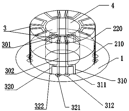
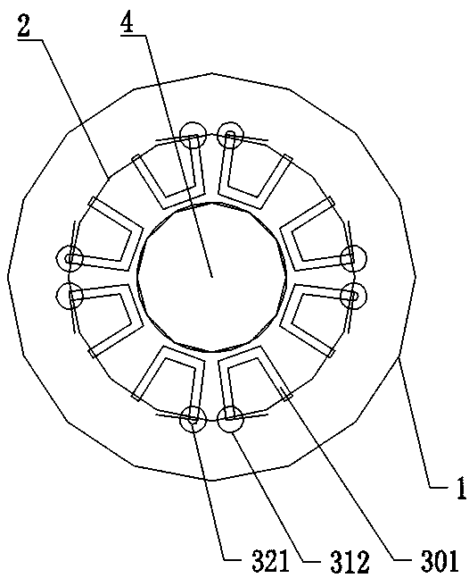
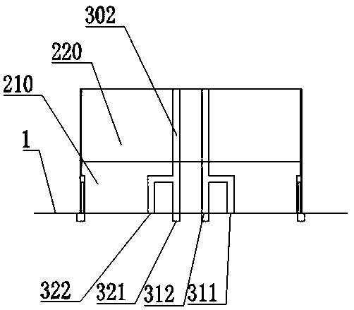
[0045] like Figure 1-4 As shown, a circularly polarized antenna device with high isolation includes: a conductive ground plane 1, a dielectric substrate 2 disposed on the conductive ground plane, and several radiation sheets disposed on the surface of the dielectric substrate;

[0046] The radiating sheet is a layer of metal conductor for receiving or transmitting signals, and the radiating sheet includes several symmetrically distributed inverted F-shaped radiating sheet groups 3, and each inverted F-shaped radiating sheet group includes an A-type inverted F-shaped radiating sheet 310 and a B-shaped inverted F-shaped radiator 320; the A-type inverted F-shaped radiator and the B-type inverted F-shaped radiator are arranged symmetrically;

[0047] The A-type inverted F-type radiation sheet and the B-type inverted F-type radiation sheet respectively include a horizontally arranged upper part 301 and a vertically arranged lower part 302, and the upper parts of the A-type inverted ...

Embodiment 2

[0060] Such as Figure 5 , this embodiment uses 4 orthogonal inverted F-type radiator groups, and each of the 2 opposite signals (with a distance of 1) undergoes a signal 180 phase shift and a 90-degree coupler combination to obtain good left-handed and right-handed Circularly polarized signal output (Hybrid180° is a coupler with a phase shift of 90°, and Hybrid90° is a coupler with a phase shift of 90°).

[0061] 4 inverted F-type radiator groups, the loss of the feed circuit is large, but the circular polarization performance is good, and the antenna is symmetrical, so the phase center is stable.


PUM


Abstract

A circularly polarized antenna device with high isolation comprises a conductive grounding plane, a dielectric substrate arranged on the conductive grounding plane and a plurality of radiation sheets arranged on the surface of the dielectric substrate. The radiation sheets are a layer of metal conductors used for receiving or transmitting signals and comprise a plurality of inverted F-shaped radiation sheet groups which are symmetrically distributed. Each inverted F-shaped radiation sheet group comprises an A-shaped inverted F-shaped radiation sheet and a B-shaped inverted F-shaped radiation sheet. Each of the A-type inverted F-type radiation sheet and the B-type inverted F-type radiation sheet comprises an upper part which is horizontally arranged and a lower part which is vertically arranged. Each A-type inverted F-type radiation sheet serves as a feed point, and each B-type inverted F-type radiation sheet serves as an open circuit. According to the invention, independent output of leftwards rotating circular polarization signals and rightwards rotating circular polarization signals is realized by adopting a plurality of the symmetrical inverted F-shaped radiation sheet groups, the isolation degree is high, the processing is simple, the size is small, the weight is light, the application requirements of receiving or transmitting dual-circular polarization signals are met, and the antenna device is particularly suitable for accurate measurement and guidance of system terminal equipment.

Description

technical field [0001] The invention belongs to the technical field of antennas, and in particular relates to a circularly polarized antenna device with high isolation. Background technique [0002] As a component used to transmit or receive radio waves, circularly polarized antennas play a vital role in wireless communication systems, especially in satellite communications and aircraft measurement and control equipment. [0003] The current satellite navigation and positioning equipment is widely used in fields such as positioning, measurement, timing, high-precision agriculture and intelligent transportation. In order to obtain high-precision positioning requirements above the decimeter level, navigation equipment generally adopts RTK (real-time dynamic differential method) technology. And axle ratio bandwidth), and more compact size, while processing and manufacturing should be simple. Due to the advantages of small shape, low cost, easy conformality, easy processing an...

Claims


Application Information

Patent Timeline
IPC IPC(8): H01Q1/36H01Q1/38H01Q1/48H01Q5/28H01Q1/52H01Q1/28
CPCH01Q1/36H01Q1/38H01Q1/48H01Q5/28H01Q1/52H01Q1/28
Inventor 李庚禄施静吴艳杰李铎张慧龙刘兆华娟
Owner 江苏三和欣创通信科技有限公司
Why Eureka
Try Eureka