
A Balanced Two-position Three-way Fuel Injection Valve

A fuel injection valve, two-position three-way technology, used in fuel injection devices, fuel injection valves driven by fluid pressure, special fuel injection devices, etc., can solve problems such as reducing dynamic oil return

Active Publication Date: 2021-06-22
FAW JIEFANG AUTOMOTIVE CO
View PDF6 Cites 0 Cited by
  • Summary
  • Abstract
  • Description
  • Claims
  • Application Information

AI Technical Summary

Problems solved by technology

[0006] The invention provides a balanced two-position three-way fuel injection valve with simple structure. The injection valve can reduce the dynamic oil return volume and improve the utilization rate of high-pressure oil; The impact on the sealing element meets the injection requirements of higher pressure and solves the above-mentioned problems existing in the existing injection valve

Method used


Image

  • A Balanced Two-position Three-way Fuel Injection Valve
  • A Balanced Two-position Three-way Fuel Injection Valve
  • A Balanced Two-position Three-way Fuel Injection Valve

Examples


Embodiment Construction

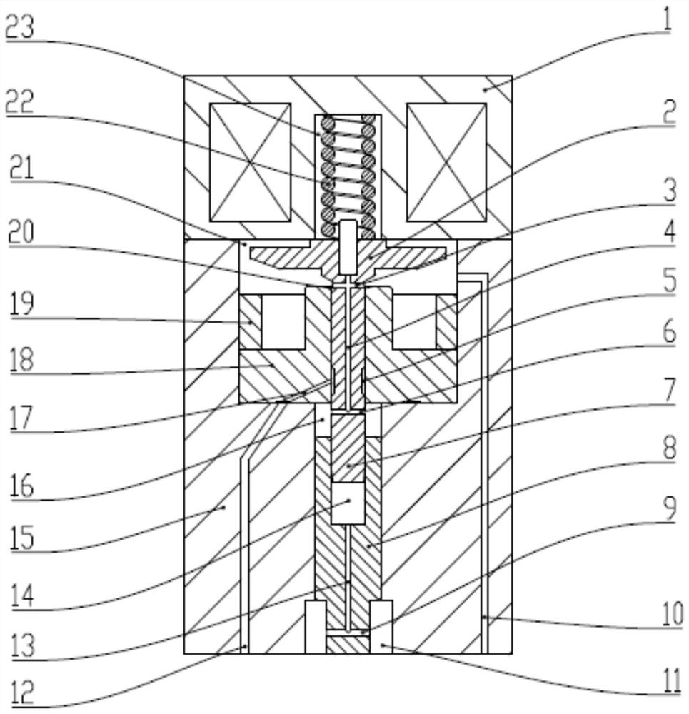
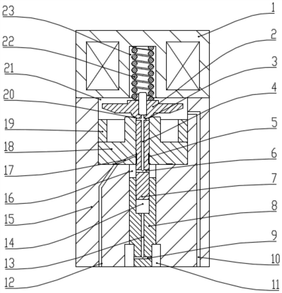
[0022] Such as figure 1 Shown in -3, the present invention mainly comprises armature 2, armature rod 7, control valve seat 18, control valve seat fixing nut 19, injector body 15, control piston 8, electromagnet 1, electromagnet spring 22.

[0023] The control valve seat 18 is pressed into the concave cavity on the upper part of the injector body 15 through the control valve seat fixing nut 19. The control valve seat 18 is provided with an oil inlet orifice 17, and one end of the hole passes through the lower part of the control valve seat. The annular groove 24 communicates with the oil inlet passage 12 on the injector body 15 , and the other end communicates with the middle hole of the control valve seat 18 .

[0024] The armature 2 and the armature rod 7 are integrally structured, and the armature rod 7 extends into the middle hole of the control valve seat 18 and can slide axially along the middle hole. The electromagnet center is provided with an electromagnet middle hole...


PUM


Abstract

The invention is a balanced two-position three-way fuel injection valve. The injection valve includes an armature, an armature rod, a control valve seat, an injector body, a control piston, an electromagnet and an electromagnet spring; the control valve seat is pressed into the cavity on the upper part of the injector body through the control valve seat fixing nut ; There is an electromagnet middle hole in the center of the electromagnet; a sealing cone is arranged at the middle hole of the upper end surface of the control valve seat; the electromagnet spring is placed in the electromagnet middle hole, and the armature is pressed tightly on the sealing cone surface. When pressed on the control valve seat, the sealing cone surface cooperates with the lower cone surface of the armature to form a line seal; the armature and the armature rod are integrated structure, and the armature rod extends into the middle hole of the control valve seat; the middle hole of the injector body The bore is provided with an axially movable control piston. The invention can reduce the dynamic oil return amount and improve the utilization rate of high-pressure oil; at the same time, it can reduce the spring preload of the control valve, improve the response, reduce the impact on the sealing element, and meet the injection requirement of higher pressure.

Description

technical field [0001] The invention belongs to the technical field of engine fuel injection valves, in particular to a balanced two-position three-way fuel injection valve. Background technique [0002] At present, the fuel injection valve of the common rail system mainly controls the opening and closing of the needle valve through a hydraulic servo mechanism. The hydraulic servo mechanism is generally composed of control valve components. The orifice plate in the control valve is provided with inlet and outlet throttle holes, and the control of the oil pressure in the control chamber is realized through the cooperation of the two throttle holes. By controlling the opening and closing of the sealing element on the oil outlet orifice of the orifice plate, the increase and decrease of the pressure in the cavity can be controlled, thereby indirectly controlling the opening and closing of the needle valve. Typical fuel injection valves are known for example from DE 19650865 A1...

Claims


Application Information

Patent Timeline
Patent Type & Authority Patents(China)
IPC IPC(8): F02M47/02F02M63/00
CPCF02M47/027F02M63/0022F02M63/0035F02M2200/304F02M2547/003
Inventor 缪金标顾小磊金昱森喻鸣显徐亚磊
Owner FAW JIEFANG AUTOMOTIVE CO
Learn More