
Electronically controlled hydraulic slottingblocking-removing reservoir modification tool

A technology of reservoir stimulation and electronically controlled hydraulic pressure, which is applied in the direction of cleaning equipment, liquid/gas jet drilling, wellbore/well components, etc., can solve the problems of perforation compaction zone pollution, insufficient perforation depth, etc. Controllable, reduced bursting pressure, and increased output

Active Publication Date: 2019-09-13
XINJIANG YONGSHENG ENERGY CO LTD
View PDF6 Cites 0 Cited by
  • Summary
  • Abstract
  • Description
  • Claims
  • Application Information

AI Technical Summary

Problems solved by technology

[0003] The purpose of the present invention is to provide an electronically controlled hydraulic slotting and plugging removal reservoir transformation tool, which can solve the problems of insufficient perforation depth and pollution in the perforation compaction zone, and increase the seepage area at the same time. The construction is simple and the cost is low. The generated fractures are easy to control, and the effect of increasing production and injection is obvious

Method used


Image

  • Electronically controlled hydraulic slottingblocking-removing reservoir modification tool
  • Electronically controlled hydraulic slottingblocking-removing reservoir modification tool
  • Electronically controlled hydraulic slottingblocking-removing reservoir modification tool

Examples


Embodiment Construction

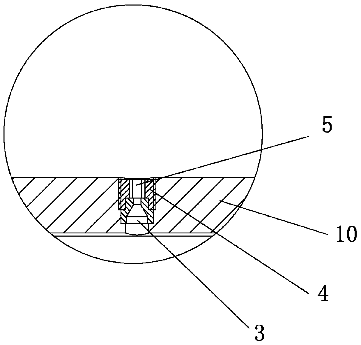
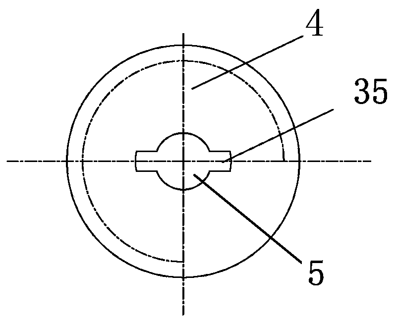
[0020] An electronically controlled hydraulic slotting and plugging removal reservoir reconstruction tool, such as figure 1 , figure 2 , image 3 As shown, it includes a reservoir stimulation valve connected to the oil pipe 13. The reservoir stimulation valve includes a casing valve seat 25, and the center hole of the casing valve seat 25 is fixedly set by a shear nail 11 perpendicular to the casing valve seat. Along with a sliding sleeve 1, the pressure relief hole 2 arranged coaxially with the shear nail is located in the pipe wall on the other side of the central hole of the sleeve valve seat, and the center of the sliding sleeve has a central through hole arranged coaxially with the central hole of the sleeve valve seat , the outer end surface of the sliding sleeve near the oil pipe is recessed and a bakelite ball 12 is housed, and the diameter of the bakelite ball 12 is greater than the aperture of the central through hole.

[0021] The lower end of the casing valve se...


PUM


Abstract

The invention discloses an electronically controlled hydraulic slottingblocking-removing reservoir modification tool capable of performing a slottingoperation on an oil well reservoir. Theelectronically controlled hydraulic slottingblocking-removing reservoir modification toolcomprises a reservoir modification valve connected to an oil pipe, the reservoir modification valve comprises a sleeve pipevalve seat and a sliding sleeve is fixedly arranged in a central hole of the sleeve pipe valve seat, and the outer side end surface, close to the oil pipe, of the sliding sleeve is recessed, and an electric wood ball is installed onthe outer side end surfaceof the sliding sleeve. The lower end of the sleeve pipevalve seat is coaxially connected with a spray gun nipple through a threaded joint,wiper blocksare evenly distributed on the axial outer peripheral wall of thespray gun nipple, and a central passage is arranged in thespray gun nipple. Nozzles are arranged on the spray gun nippleon thefrontsides and rear sides of the wiper blocks, and the two nozzles are arranged in a 90-degree-included-angle mode. The lower end of the spray gun nipple is connected to a well washing guide shoe by athreaded joint, and the lower end of the well washing guide shoe is closed, a backwashing passage is arranged at the center shaft position of the well washing guide shoe, a steel ball is arranged atthe liquid inlet end of the backwashing channel, and four liquid outlets are formed in thebackwashing passage.

Description

technical field [0001] The invention relates to an electronically controlled hydraulic slotting and plugging removal reservoir transformation tool capable of performing slotting operations on oil well reservoirs. Background technique [0002] In oilfield production operations, in order to increase the permeability of the formation around the wellbore, it is often necessary to cut the formation near the wellbore by jetting high-pressure water. The existing conventional cutting tools have the problems of insufficient perforation depth and contamination of the perforation compaction zone, the resulting cracks are not easy to control, and the effect of increasing production and injection is not obvious. Moreover, the erosion of water flow and gravel often causes great impact and damage to casing and cement sheath. Contents of the invention [0003] The purpose of the present invention is to provide an electronically controlled hydraulic slotting and plugging removal reservoir...

Claims


Application Information

Patent Timeline
IPC IPC(8): E21B7/18E21B37/00
CPCE21B7/18E21B37/00
Inventor 董琪肖舒月徐旭李新强李情霞史源源李良吴浩刘伟何飞
Owner XINJIANG YONGSHENG ENERGY CO LTD
Learn More