Dynamic fixing device through posterior cervical approach

A fixation device and posterior approach technology, applied in the direction of fixator, internal fixator, internal bone synthesis, etc., can solve the problems of reduced cervical spine stability, cervical spine axial pain, door opening shaft fracture, etc., to reduce postoperative complications, The effect of expanding the space of the spinal canal and improving the stability

Pending Publication Date: 2019-09-13
SHANGHAI NINTH PEOPLES HOSPITAL AFFILIATED TO SHANGHAI JIAO TONG UNIV SCHOOL OF MEDICINE
View PDF0 Cites 2 Cited by
  • Summary
  • Abstract
  • Description
  • Claims
  • Application Information

AI Technical Summary

Problems solved by technology

Complications such as incomplete molding, fracture of the door opening shaft, and axial pain of the cervical spine commonly exist in the existing fixed plate used for the above-mentioned decompression plastic surgery, which affect the curative effect of the surgery
[0004] For total laminar decompression therapy, there is a lack of muscle and ligament support structure. The separation of muscle and ligament from the cervical spinous process will lead to a decrease in the adhesion of soft tissues such as ligaments after surgery, and insufficient support will lead to a decrease in cervical spine stability and deformity.

Method used


Image

  • Dynamic fixing device through posterior cervical approach
  • Dynamic fixing device through posterior cervical approach
  • Dynamic fixing device through posterior cervical approach

Examples


Embodiment Construction

[0024] Below in conjunction with specific embodiment, further illustrate the present invention. It should be understood that these examples are only used to illustrate the present invention and are not intended to limit the scope of the present invention. In addition, it should be understood that after reading the teachings of the present invention, those skilled in the art can make various changes or modifications to the present invention, and these equivalent forms also fall within the scope defined by the appended claims of the present application.

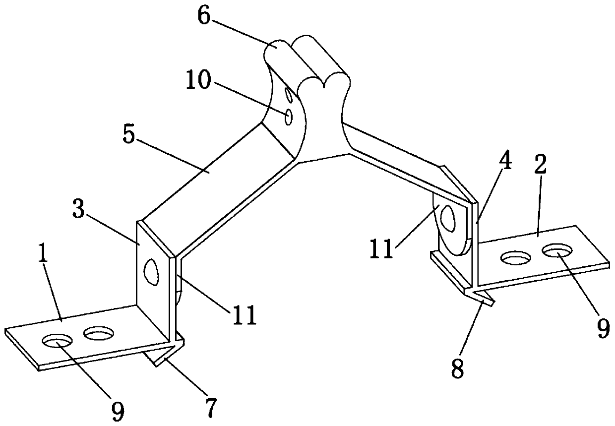
[0025] Such as figure 1 A posterior cervical dynamic fixation device shown includes a first bone plate 1, a second bone plate 2, a first cavity expansion plate 3, a second cavity expansion plate 4, an imitation vertebral plate 5, an imitation spinous process 6, a first A supporting foot 7 and a second supporting foot 8. The first bone plate 1, the second bone plate 2, the first expansion plate 3, the second expansion plate 4,...


PUM


Abstract

The invention relates to a dynamic fixing device through a posterior cervical approach. The device includes a first internal fixation plate and a second internal fixation plate, a first supporting foot is arranged at the bottom of the first internal fixation plate, a second supporting foot is arranged at the bottom of the second internal fixation plate, and fixing holes are arranged on the first internal fixation plate and the second internal fixation plate, respectively; the device also includes a first cavity expanding plate and a second cavity expanding plate, a simulated vertebral plate and a simulated spinous process, the first cavity expanding plate is vertically connected to the first internal fixation plate, the second cavity expanding plate is vertically connected to the second internal fixation plate, two sides of the simulated vertebral plate are rotatably connected to the first cavity expanding plate and the second cavity expanding plate, respectively, the simulated spinousprocess is located at the top of the simulated vertebral plate, and the simulated spinous process is provided with ligament attachment suture holes. The invention can expand and reconstruct the vertebral canal environment of the patient, provide effective protections and maintain extension and flexion activity of cervical vertebra, and can provide stable support and attachment for muscles and ligaments of the patient after operation, help the recovery of normal biomechanics of the cervical vertebra after operation and reduce postoperative complications.

Description

technical field [0001] The invention belongs to the technical field of total lamina decompression and fixation in the posterior cervical approach, and in particular relates to a dynamic fixation device in the posterior cervical approach. Background technique [0002] Cervical spondylosis is a common disease. The causes of the disease include cervical disc herniation, ligament thickening, spinal canal stenosis, trauma, etc. Some cervical spondylosis can be treated with posterior cervical spinal canal expansion and plastic surgery to obtain good therapeutic effect. [0003] Existing posterior cervical spinal canal enlargement and decompression therapy includes single-door molding, double-door molding, and total laminectomy. Corresponding fixing plates are required to support and fix the lamina during the operation. Complications such as incomplete molding, fracture of the door opening shaft, and axial pain of the cervical spine commonly exist in the existing fixation plate use...

Claims


Application Information

Patent Timeline
IPC IPC(8): A61B17/70
CPCA61B17/7062
Inventor 丁宝志赵杰
Owner SHANGHAI NINTH PEOPLES HOSPITAL AFFILIATED TO SHANGHAI JIAO TONG UNIV SCHOOL OF MEDICINE
Why Eureka
Try Eureka