A low-power electronic transformer

An electronic transformer, low power consumption technology, applied in transformers, fixed transformers, transformer/inductor cooling, etc., can solve the problems of limited installation space manufacturing cost, general air cooling and heat dissipation performance, poor dustproof and noise reduction performance, etc. Compact structure, good heat conduction and cooling effect, and the effect of eliminating heat insulation gaps

Active Publication Date: 2020-12-01
XIAMEN YIKE ELECTRONICS
View PDF7 Cites 0 Cited by
  • Summary
  • Abstract
  • Description
  • Claims
  • Application Information

AI Technical Summary

Problems solved by technology

[0004] Traditional small and medium-sized electronic transformers usually use air cooling as the main means of cooling. However, due to the existence of fans and the characteristics of external installation, the performance of air cooling and heat dissipation is generally poor, and the performance of dust and noise reduction is poor. Immersion cooling method, however, because small and medium-sized electronic transformers are generally installed inside the equipment, the installation space and design and manufacturing costs are limited, it is impossible to separately equip a complete oil circulation cooling system to cool the cooling oil like large oil-immersed transformers. Real-time cooling and oil replacement. Oil-cooled electronic transformers generally inject oil into the top opening of the transformer and set a cover. Therefore, the fixed installation of oil-cooled electronic transformers mainly has the following technical defects: 1. When the transformer is regularly maintained and replaced with cooling oil, It is necessary to disassemble the transformer and open the cover to discharge the oil. The operation steps are cumbersome and difficult to operate; 2. The inner cavity of the transformer is absolutely closed under the working state, and the increase of internal temperature rise and pressure may lead to deformation of the sealing structure and leakage of oil Leakage, even burst safety hazards

Method used


Image

  • A low-power electronic transformer
  • A low-power electronic transformer
  • A low-power electronic transformer

Examples


Embodiment Construction

[0051] The technical solutions in the embodiments of the invention will be clearly and completely described below in conjunction with the accompanying drawings in the embodiments of the invention. Obviously, the described embodiments are only part of the embodiments of the invention, not all of them. Based on the embodiments of the invention, all other embodiments obtained by persons of ordinary skill in the art without making creative efforts belong to the protection scope of the invention.

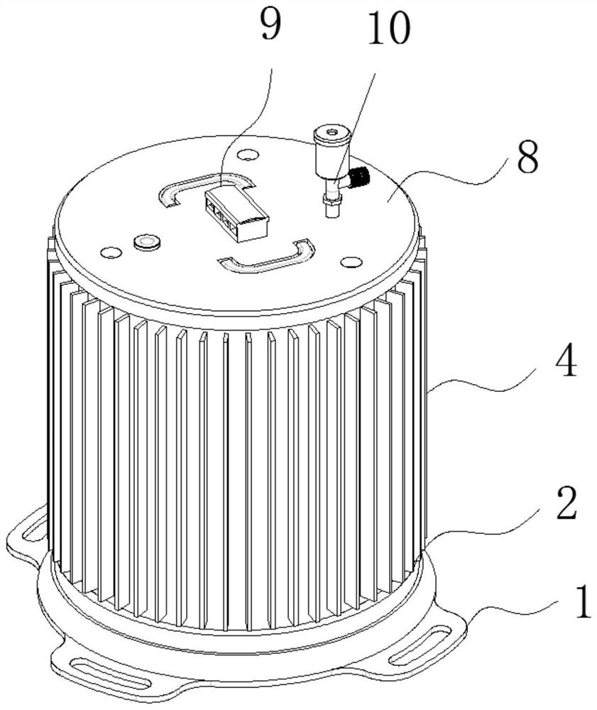
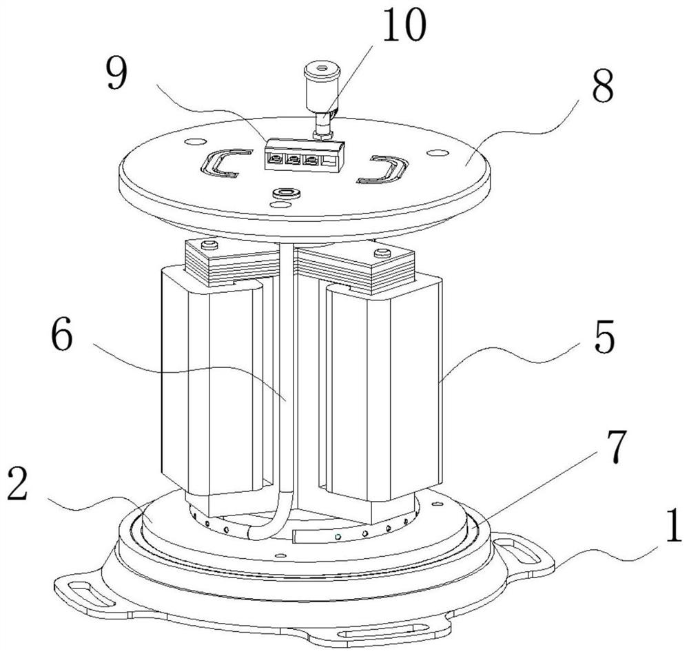
[0052] see Figure 1-17 , the invention provides a technical solution: a low-power electronic transformer, which mainly includes an installation chassis 1, a bottom end cover seat 2, a connection shell 3, a heat dissipation shell 4, a core body 5, an oil filling pipe 6, a sealing ring 7, and a top end The cover base 8, the terminal row 9 and the oil discharge pipe 10, the installation chassis 1 is coaxially installed on the bottom of the bottom end cover base 2 through screws, the core b...


PUM

PropertyMeasurementUnit
thicknessaaaaaaaaaa
thicknessaaaaaaaaaa

Abstract

The invention discloses a low-power electronic transformer, and belongs to the technical field of electronic transformers. The low-power electronic transformer mainly comprises a mounting chassis, a bottom end cover seat, a connecting shell, a heat dissipation shell, a wire core main body, an oil injection pipe, sealing rings, a top end cover seat, a wiring terminal bar and an oil discharge pipe;the mounting chassis is coaxially mounted at the bottom of the bottom end cover seat through screws; the wire core main body is mounted at the top of the bottom end cover seat through main body screws; the upper end and the lower end of the connecting shell are connected and fixed to the top end cover seat and the bottom end cover seat through screws respectively; the sealing rings are arranged atthe joints of the two ends of the connecting shell; the heat dissipation shell sleeves the outer wall of the connecting shell in an attached mode; the top end of the oil injection pipe communicates with the top end cover seat; the lower end of the oil injection pipe extends into the bottom of the wire core main body; the wiring terminal bar is mounted in the center of the top of the top end coverseat in an embedded manner and is electrically connected with the wire core main body; and the top of the top end cover seat is provided with the oil discharge pipe. The three-phase electronic transformer is capable of effectively reducing the power consumption.

Description

technical field [0001] The invention relates to the technical field of electronic transformers, in particular to a low-power electronic transformer. Background technique [0002] An electronic transformer is an electronic device that converts the AC voltage of the mains into DC and then forms a high-frequency AC voltage output through semiconductor switching devices, electronic components and high-frequency transformer windings. It is also an electronic device described in electronics theory. An AC-DC-AC inverter circuit. Transformer loss is a concept in the field of modern physics, which refers to the sum of no-load loss (iron loss), short-circuit loss (copper loss) and stray loss. The no-load loss of the transformer is due to the eddy current generated inside the iron core during operation. When the eddy current passes through the iron core, heat energy will be generated inside the iron core. This heat energy consumes energy, so it is called "iron loss". In addition, a l...

Claims


Application Information

Patent Timeline
Patent Type & Authority Patents(China)
IPC IPC(8): H01F30/12H01F27/28H01F27/02H01F27/12H01F27/14
CPCH01F27/02H01F27/025H01F27/12H01F27/14H01F27/28H01F27/2876H01F30/12
Inventor 马善鸿
Owner XIAMEN YIKE ELECTRONICS
Why Eureka
Try Eureka