
Support for blade of wind driven generator

A technology for wind turbines and blades, applied in wind turbines, wind energy power generation, engines, etc., can solve the problems of reduced bearing capacity, long curing time, low bonding strength, etc., achieve good force absorption characteristics, avoid peeling stress, and improve The effect of bond strength

Active Publication Date: 2019-09-10
YUANJIAN WIND POWER JIANGYINENVISION ENERGY CO LTD
View PDF6 Cites 3 Cited by
  • Summary
  • Abstract
  • Description
  • Claims
  • Application Information

AI Technical Summary

Problems solved by technology

However, existing stents are difficult to meet both flexibility and strength requirements
Some stent bodies are strong but not flexible enough
In order to meet the deformation requirements of the blade root, the bracket and the baffle are bonded with flexible adhesive, but the process requirements are high, the cost is high, the curing time is long, and the bonding strength is low (for example, the strength is only 1 / 10 of the structural adhesive). The bearing capacity drops sharply, which easily causes safety risks such as baffle falling off or blade damage
Other brackets are more flexible but not strong enough to provide adequate support for the baffle along the length of the blade

Method used


Image

  • Support for blade of wind driven generator
  • Support for blade of wind driven generator
  • Support for blade of wind driven generator

Examples


Embodiment Construction

[0046]It should be noted that components in the various figures may be shown exaggerated for the purpose of illustration and are not necessarily true to scale. In the various figures, identical or functionally identical components are assigned the same reference symbols.

[0047] In the present invention, unless otherwise specified, "arranged on", "arranged on" and "arranged on" do not exclude the presence of intermediates between the two. In addition, "arranged on or above" only means the relative positional relationship between two parts, and under certain circumstances, such as after the product direction is reversed, it can also be converted to "arranged under or below", and vice versa Of course.

[0048] In the present invention, each embodiment is only intended to illustrate the solutions of the present invention, and should not be construed as limiting.

[0049] In the present invention, unless otherwise specified, the quantifiers "a" and "an" do not exclude the scene...


PUM

PropertyMeasurementUnit
widthaaaaaaaaaa
thicknessaaaaaaaaaa
lengthaaaaaaaaaa

Abstract

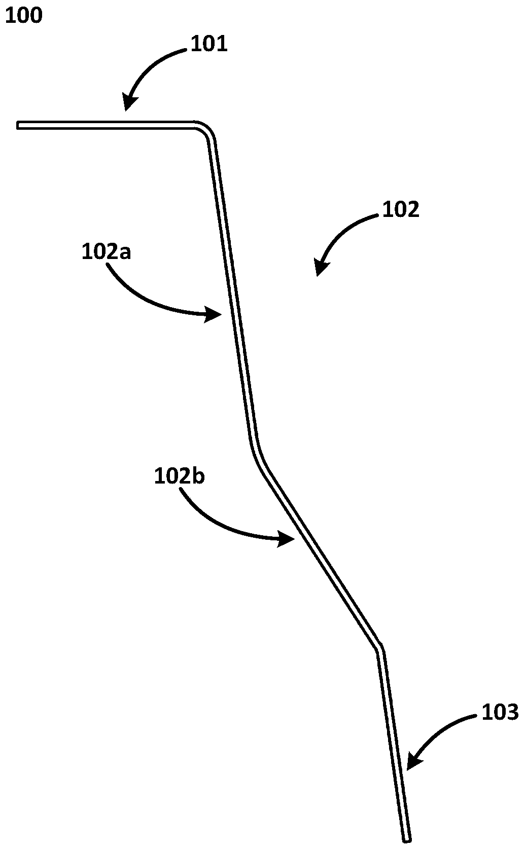
The invention relates to a support for a blade of a wind driven generator. The support comprises a baffle bonding flange, a flexible connecting unit and a shell bonding flange, the baffle bonding flange can be connected with a baffle of the wind driven generator through a binding agent, the flexible connecting unit is provided with a first connecting unit and a second connecting unit, one end of the first connecting unit is connected with the baffle bonding flange, the other end of the first connecting unit is connected with the second connecting unit, an included angle between the first connecting unit and the baffle bonding flange is 90 degrees or above, one end of the second connecting unit is connected with the first connecting unit, the other end of the second connecting unit is connected with the shell bonding flange, the included angle between the first connecting unit and the second connecting unit is larger than 0 degree, the shell bonding flange can be connected with the rootof the blade of the wind driven generator through a binding agent, and the included angle between the shell bonding flange and the second connecting unit is 90 degrees or above. According to the support for the blade of the wind driven generator, enough supporting force can be provided for the blade in the length direction of the blade, and meanwhile, flexible connection between the blade and thebaffle is provided so that the deformation of the root of the blade can be well absorbed.

Description

technical field [0001] The present invention generally relates to the field of wind power generators, and in particular, relates to a bracket for a blade of a wind power generator. In addition, the invention also relates to a wind generator using the support and a method for installing the support. Background technique [0002] In recent years, the field of clean energy has shown a trend of rapid development. As a new type of energy, clean energy has the advantages of wide distribution, renewable, and less environmental pollution compared with traditional fossil fuels. As a representative of clean energy, the application of wind power generators is increasing day by day. [0003] The blades of wind turbines are important components for wind turbines to capture wind energy, and their operating status is directly related to equipment safety and power generation efficiency. The root of the blade is generally installed with a baffle for internal sealing of the blade and provi...

Claims


Application Information

Patent Timeline
Patent Type & Authority Applications(China)
IPC IPC(8): F03D80/00B29C70/36B29C65/48B32B17/02B32B17/12
CPCB29C65/48B29C70/36B32B5/02B32B5/26B32B17/067B32B2250/20B32B2262/101F03D80/00Y02E10/72
Inventor J·A·格鲁张向阳邹维杰R·迪艾宝
Owner YUANJIAN WIND POWER JIANGYINENVISION ENERGY CO LTD
Learn More