Nd-Fe-B magnetic powder material-mixing machine
A mixing machine, NdFeB technology, applied in the direction of mixers, mixers with rotating containers, mixer accessories, etc., can solve the problems of slow mixing speed, uneven mixing, etc., and achieve the effect of convenient use
- Summary
- Abstract
- Description
- Claims
- Application Information
AI Technical Summary
Problems solved by technology
Method used
Image
Examples
Embodiment 1
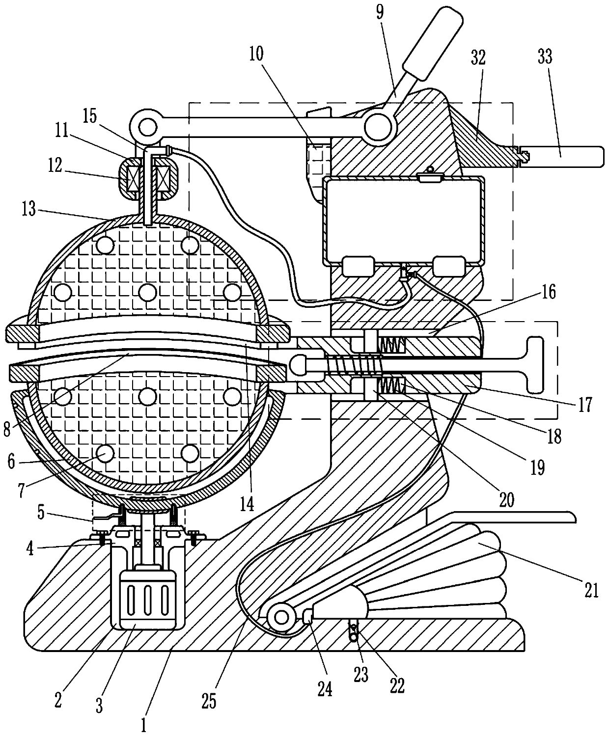
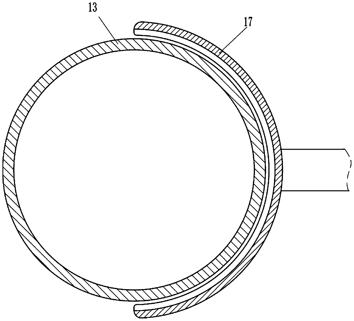
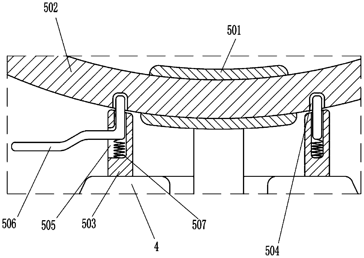
[0023] As attached figure 1 , Attached figure 2 And image 3 As shown, a neodymium-iron-boron magnetic powder mixer includes a mounting frame 1, a geared motor 3, a protective frame 4, a sliding device 5, a lower mixing ball 6, an iron column 7, a pry bar 9, a support block 10, a buckle Tightening device, injection pipe 15 and fixing device, the top left side of the mounting frame 1 is provided with a first groove 2, a geared motor 3 is installed in the first groove 2, and a bolt is passed on the mounting frame 1 outside the first groove 2 A protective frame 4 that can fix the geared motor 3 is installed. The protective frame 4 is provided with a sliding device 5 that facilitates taking out the mixed magnetic powder. The output shaft of the geared motor 3 passes through the protective frame 4 and is connected to the sliding device 5. There is a lower mixing ball 6, five iron posts 7 welded in the lower mixing ball 6, an annular groove 8 is opened on the top of the lower mixing ...
Embodiment 2
[0028] As attached figure 1 , Attached figure 2 And image 3 As shown, a neodymium iron boron magnetic powder mixing machine, the fastening device includes a connecting block 11, a bearing seat 12, an upper mixing ball 13 and an annular protrusion 14. The left end of the pry bar 9 is provided with a connecting block 11 which is connected A bearing seat 12 is provided in the block 11, an upper mixing ball 13 is provided in the bearing seat 12, and an annular protrusion 14 is provided at the bottom of the upper mixing ball 13. The annular protrusion 14 is elastic, and the annular protrusion 14 is matched with the annular groove 8. , The liquid injection pipe 15 is arranged in the connecting block 11, the liquid injection pipe 15 passes through the top of the upper mixing ball 13, the top of the upper mixing ball 13 is hollow, and the liquid injection pipe 15 is not connected with the upper mixing ball 13.
[0029] The working principle of the present invention: when the lower mixin...
Embodiment 3
[0033] As attached figure 1 And Figure 4 As shown, it also includes a stepped wind box 21, a suction pipe 22, a first one-way valve 23, an air outlet pipe 24, a first hose 25, an oil storage tank 26, a plug 27, an oil outlet pipe 28, a second hose 29, For the second one-way valve 30 and the third one-way valve 31, a pedal-type bellows 21 is installed at the lower part of the mounting frame 1, a suction pipe 22 is connected to the bottom of the pedal-type bellows 21, and a first check valve 23 is provided in the suction pipe 22 The left end of the stepped wind box 21 is provided with an air outlet pipe 24, the end of the air outlet pipe 24 is connected with a first hose 25, the upper part of the mounting frame 1 is installed with an oil storage tank 26 through bolts, the top of the oil storage tank 26 is plugged with a plug 27, and the bottom of the oil storage tank 26 An oil outlet pipe 28 is provided. The bottom end of the oil outlet pipe 28 is connected with a second hose 29....
PUM
 Abstract
Description
Claims
Application Information
 - R&D Engineer
- R&D Manager
- IP Professional
- Industry Leading Data Capabilities
- Powerful AI technology
- Patent DNA Extraction
Browse by: Latest US Patents, China's latest patents, Technical Efficacy Thesaurus, Application Domain, Technology Topic, Popular Technical Reports.
© 2024 PatSnap. All rights reserved.Legal|Privacy policy|Modern Slavery Act Transparency Statement|Sitemap|About US| Contact US: help@patsnap.com


