Rotary vortex jetting tray

A technology of tray and jet tube, applied in the field of rotating vortex jet tray, can solve the problems of high operating conditions, low gas-liquid two-phase turbulence, low operating elasticity, etc., and achieve the effect of strengthening mass transfer conditions

Inactive Publication Date: 2019-09-10
范锦红
View PDF0 Cites 1 Cited by
  • Summary
  • Abstract
  • Description
  • Claims
  • Application Information

AI Technical Summary

Problems solved by technology

For example, liquid leakage on the tray, difficult to increase the gas-liquid contact time and area, "back-mixing" of the liquid flow on the plate, liquid level drop, mist entrainment, low gas-liquid two-phase turbulence, low operating flexibility, and high requirements for operating conditions, etc.
More importantly, the mass transfer rate is limited to the low-speed mass transfer range dominated by "molecular diffusion", and it is difficult to improve the tray efficiency.

Method used


Image

  • Rotary vortex jetting tray
  • Rotary vortex jetting tray
  • Rotary vortex jetting tray

Examples


Embodiment Construction

[0037] 1. One-time sale.

[0038] 2. Cooperative development.

[0039] 【Note 1】

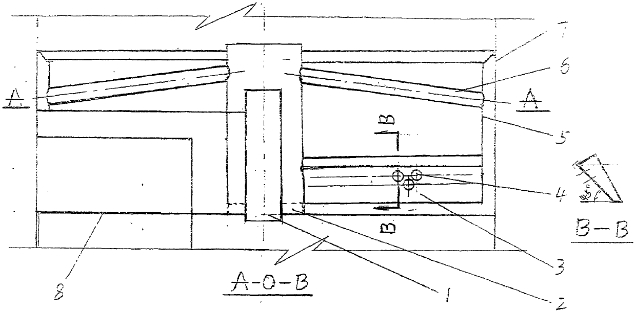
[0040] About the gas flow resistance of the rectification column. The resistances that need to be overcome for gas flow in this tower include: the resistance of the two-way liquid layer above the nozzle hole, the resistance of the vortex flow pressure, the resistance of the dry plate, and the resistance caused by the surface tension, viscosity and gravity of the liquid. Among them, the first three items are larger than the existing tray tower.

[0041] On the same tray, the concentration of volatile components gradually decreases in the direction of liquid flow. As a result, the concentration of the gas under the plate is always constant, and the low-volatile components and the volatile components in the liquid phase are continuously provided for mass exchange. With the lengthening of the liquid flow path, the liquid that should have overflowed like a conventional column continues to contact ...


PUM


Abstract

This invention relates to a tray for mass transfer absorption columns and rectification columns in the chemical industry. The tray includes a radial jetting pipe or a jetting hood, a tray plate, and the like. Ascending gas enters the jetting pipe or the jetting hood through ascending and descending gas passages, and is then jetted from jetting holes in a high speed to generate a large amount of vortexes artificially; after liquid is pushed by the gas to rotate by nearly a round, the liquid enters a tray of the next layer through a fan-shaped overflow pipe. The tray overcomes a plurality of disadvantages of existing trays, greatly increases the contact time and area of gas and liquid phases by utilizing the vertex function, and greatly increases the tray efficiency and the operation flexibility. A heat transfer device can be additionally arranged on the tray. The tray is applicable to pressurized and vacuum absorption columns and various distillation columns.

Description

[0001] Technical field: [0002] Trays for mass transfer absorption towers and rectification towers in the chemical industry [0003] Background technique: [0004] At present, the functions of the mass transfer trays used in the chemical industry at home and abroad are all limited to the role of trays. Both must drill holes in the tray. During operation, it is required that the gas can rise smoothly from the hole, and the liquid cannot leak from the hole. Therefore produced a series of insurmountable disadvantages. For example, liquid leakage on the tray, difficult to increase the gas-liquid contact time and area, "back-mixing" of the liquid flow on the plate, liquid level drop, mist entrainment, low gas-liquid two-phase turbulence, low operating flexibility, and high operating conditions. More importantly, the mass transfer rate is limited to the low-speed mass transfer range dominated by "molecular diffusion", and it is difficult to improve the tray efficiency. However, ...

Claims


Application Information

Patent Timeline
Patent Type & Authority Applications(China)
IPC IPC(8): B01D53/18B01D3/18
CPCB01D3/18B01D53/185
Inventor 刘龙畴
Owner 范锦红
Why Eureka
Try Eureka