Wheel flaw detector auxiliary device based on gear linkage principle

A wheel flaw detection and gear linkage technology, applied in measuring devices, instruments, scientific instruments, etc., can solve the problems of authenticity error of detection data, reduce service life, increase the degree of spindle wear, etc., achieve convenient operation, improve stability, and save work. effect of time

Inactive Publication Date: 2019-09-06
阮晓媚
View PDF3 Cites 2 Cited by
  • Summary
  • Abstract
  • Description
  • Claims
  • Application Information

AI Technical Summary

Problems solved by technology

[0002] When using a flaw detector to detect tires, it is necessary to ensure that the position of the tire remains unchanged during the detection process. If the position of the tire changes or shifts during the detection process, the position of the detection point may change, and the operator needs to re-adjust the tire. Positioning and re-calibrating the detection points will seriously affect the progress of the detection work and prolong the detection cycle. At the same time, if the tire deflects, it may affect the accuracy of the detection results, making the authenticity of the detection data difficult big error
[0003] At the same time, the existing jaw-type tire clamping device generally needs to change the rotation direction of the main shaft to tighten or loosen the jaws. During the detection process, it is necessary to frequently change the rotation direction of the main shaft, which may Lead to increased wear of the spindle, reducing the service life of the unit

Method used


Image

  • Wheel flaw detector auxiliary device based on gear linkage principle
  • Wheel flaw detector auxiliary device based on gear linkage principle
  • Wheel flaw detector auxiliary device based on gear linkage principle

Examples


Embodiment Construction

[0030] The following will clearly and completely describe the technical solutions in the embodiments of the present invention with reference to the accompanying drawings in the embodiments of the present invention. Obviously, the described embodiments are only some, not all, embodiments of the present invention. Based on the embodiments of the present invention, all other embodiments obtained by persons of ordinary skill in the art without making creative efforts belong to the protection scope of the present invention.

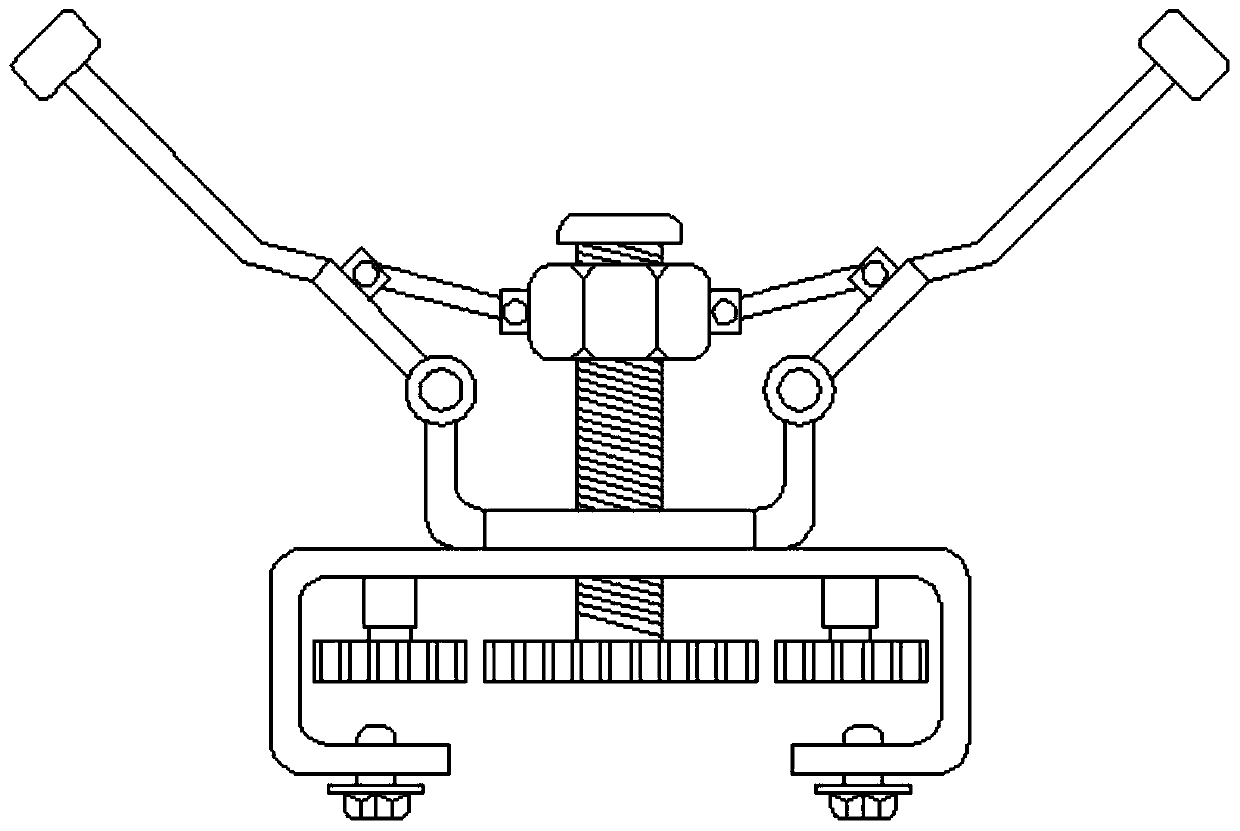
[0031] see Figure 1-7 :

[0032] The wheel flaw detector auxiliary device based on the principle of gear linkage includes a base plate 1, a movable screw group 2, a fixed screw rod 3, a limit seat 4, a connecting rod 5, a movable rod 6, a block 7, a frame 8, a driven gear 9, Transmission gear one 10, transmission gear two 11, adjustment mechanism 12, forward gear set 13, reverse gear set 14, forward gear one 15, forward gear two 16, reverse gear one 17 and rev...


PUM


Abstract

The invention relates to the technical field of automobile detection auxiliary equipment, provides a wheel flaw detector auxiliary device based on a gear linkage principle. The auxiliary device comprises a bottom plate; a movable screw group is connected to the front side of the bottom plate; a fixed screw is connected to the movable screw group and penetrates the bottom plate; and the bottom of the fixed screw is fixedly connected with a driven gear. The central axes of the bottom plate, the movable screw group and the fixed screw are arranged at the same straight line. Four limiting seats are fixedly connected to the outer side of the bottom plate. According to the auxiliary device, when the movable screw group moves upward, the distance between clamp blocks is reduced to clamp a tyre; when the movable screw group moves downward, the distance between clamp blocks is increased to take out the tyre after detection completion. On the basis of the structure and process, the tyre can be clamped and fixed by the device; the operation becomes convenient and thus certain working time is saved; the accuracy of the detection result is improved and the work efficiency is enhanced.

Description

technical field [0001] The invention relates to the technical field of automobile detection auxiliary equipment, in particular to an auxiliary device for a wheel flaw detector based on the principle of gear linkage. Background technique [0002] When using a flaw detector to detect tires, it is necessary to ensure that the position of the tire remains unchanged during the detection process. If the position of the tire changes or shifts during the detection process, the position of the detection point may change, and the operator needs to re-adjust the tire. Positioning and re-calibrating the detection points will seriously affect the progress of the detection work and prolong the detection cycle. At the same time, if the tire deflects, it may affect the accuracy of the detection results, making the authenticity of the detection data difficult big error. [0003] At the same time, the existing jaw-type tire clamping device generally needs to change the rotation direction of ...

Claims


Application Information

Patent Timeline
IPC IPC(8): G01N33/44
CPCG01N33/445
Inventor 阮晓媚
Owner 阮晓媚
Why Eureka
Try Eureka