Emergency blocking door
A technology for blocking doors and gates, which is applied in mining equipment, building fastening devices, mining equipment, etc., can solve the problems of low reliability and safety, achieve high reliability and safety, improve safety and reliability, The effect of improving the blocking ability
- Summary
- Abstract
- Description
- Claims
- Application Information
AI Technical Summary
Problems solved by technology
Method used
Image

Examples
Embodiment 1
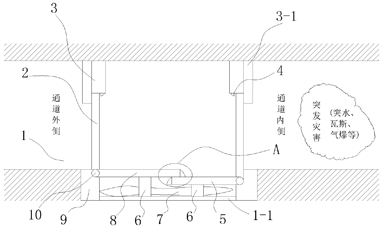
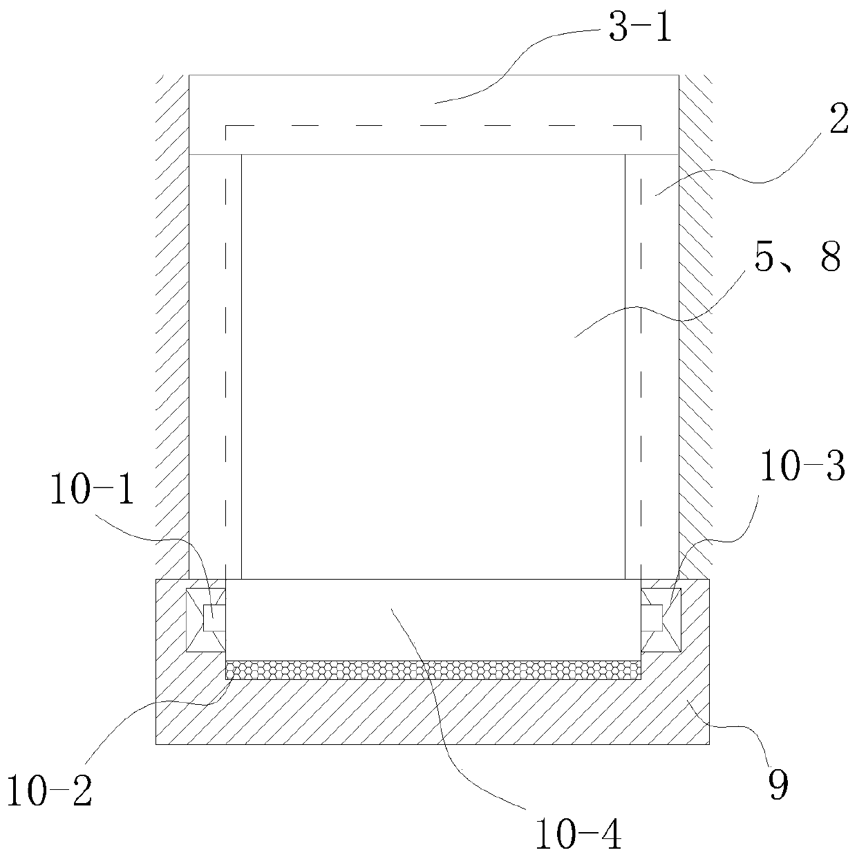
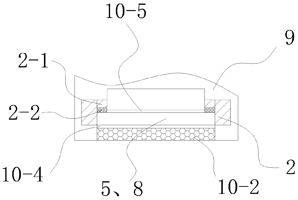
[0057] Embodiment one, with reference to Figure 1-10 , an emergency blocking door, comprising two door frames 2, the two door frames 2 are fixed side by side on the channel 1, the channel 1 between the two door frames 2 is respectively provided with an outer gate 8 and an inner gate 5, and the channel 1 The support plate 1-1 provided corresponding to the channel support surface, the support plate 1-1 is embedded in the channel support surface, the channel support surface in this embodiment is the bottom surface of the channel, and the inner and outer ends of the support plate 1-1 are respectively set There are abutments 9, and the two door frames 2 are respectively fixed on the abutments 9 at both ends of the support plate 1-1, and the hinged ends of the outer gate 8 and the inner gate 5 are respectively installed on the corresponding abutments 9 at the bottom of the door frame 2 through fixed hinge seats 10, The fixed hinge seat 10 includes a rotating cylinder 10-4, which is...
Embodiment 2
[0064] Embodiment two, refer to Figure 11 , this embodiment adds the following technical features on the basis of Embodiment 1:
[0065] Also comprises unlocking mechanism, and unlocking mechanism comprises outer door unlocking handwheel 23, and outer door unlocking handwheel 23 is arranged on the outer door head frame 3, and corresponding lock column 4 is arranged, and outer door unlocking handwheel 23 is connected with unlocking shaft 24, and the outer door unlocking handwheel 23 is connected with unlocking shaft 24, and The top of the door head frame 3 corresponding to the vertical groove 41 is provided with an outer door chute 14, the outer door chute 14 is provided with an unlocking rack 11, the bottom end of the unlocking rack 11 is fixedly connected with the top of the lock cylinder 4, and the unlocking shaft 24 is horizontal Through the outer door chute 14 and supported in the door frame 3 by the fixed bearing 12, the unlocking shaft 24 in the outer door chute 14 is e...
Embodiment 3
[0068] Embodiment three, refer to Figure 12 , this embodiment adds the following technical features on the basis of the second embodiment: the operation handwheel 94 is installed in the abutment 9 corresponding to the outer gate 8 and installed in the abutment 9 corresponding to the outer gate 8 On the handwheel frame 93, the outer end of the operation handwheel 94 is connected with the operation handle 91 on the operation handwheel shaft 92; the operation handwheel 94 is wound with a decompression stay cord 95, and the air bag 7 is provided with an air outlet 71, reducing the pressure. The outer end of the pull rope 95 stretches out from the abutment 9 and is connected with the sealing plug 72; when the inner and outer gates need to be opened, it is convenient to deflate and decompress the airbag 7.
PUM
 Abstract
Description
Claims
Application Information
 - R&D
- Intellectual Property
- Life Sciences
- Materials
- Tech Scout
- Unparalleled Data Quality
- Higher Quality Content
- 60% Fewer Hallucinations
Browse by: Latest US Patents, China's latest patents, Technical Efficacy Thesaurus, Application Domain, Technology Topic, Popular Technical Reports.
© 2025 PatSnap. All rights reserved.Legal|Privacy policy|Modern Slavery Act Transparency Statement|Sitemap|About US| Contact US: help@patsnap.com