


Quick Research
Generate reliable direction feasibility study reports for your R&D in just a few steps.

Technical Q&A
Discover and master advanced knowledge NOW. Basics, ideas, possibilities, all at once.

Find Solutions
As an expert in R&D theories, this can generate solutions to your technical problems instantly.

Evaluate Feasibility
Analyze your overall solution with one click, know your potential R&D risks in advance.

Monitor Landscape
Get weekly tech updates, stay abreast of the latest tech innovations and key insights.
Double-rotor yoke-free radial magnetic flux direct-cooling motor
A technology of radial magnetic flux and double rotors, which is applied in the direction of magnetic circuit rotating parts, magnetic circuits, electric components, etc., can solve the problems of high motor cost and power density, and achieves ingenious structure, reasonable design, and solution The effect of cooling bottlenecks
- Summary
- Abstract
- Description
- Claims
- Application Information
AI Technical Summary
Problems solved by technology
Method used
Image

Examples
Embodiment 1
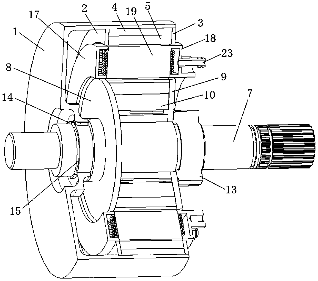
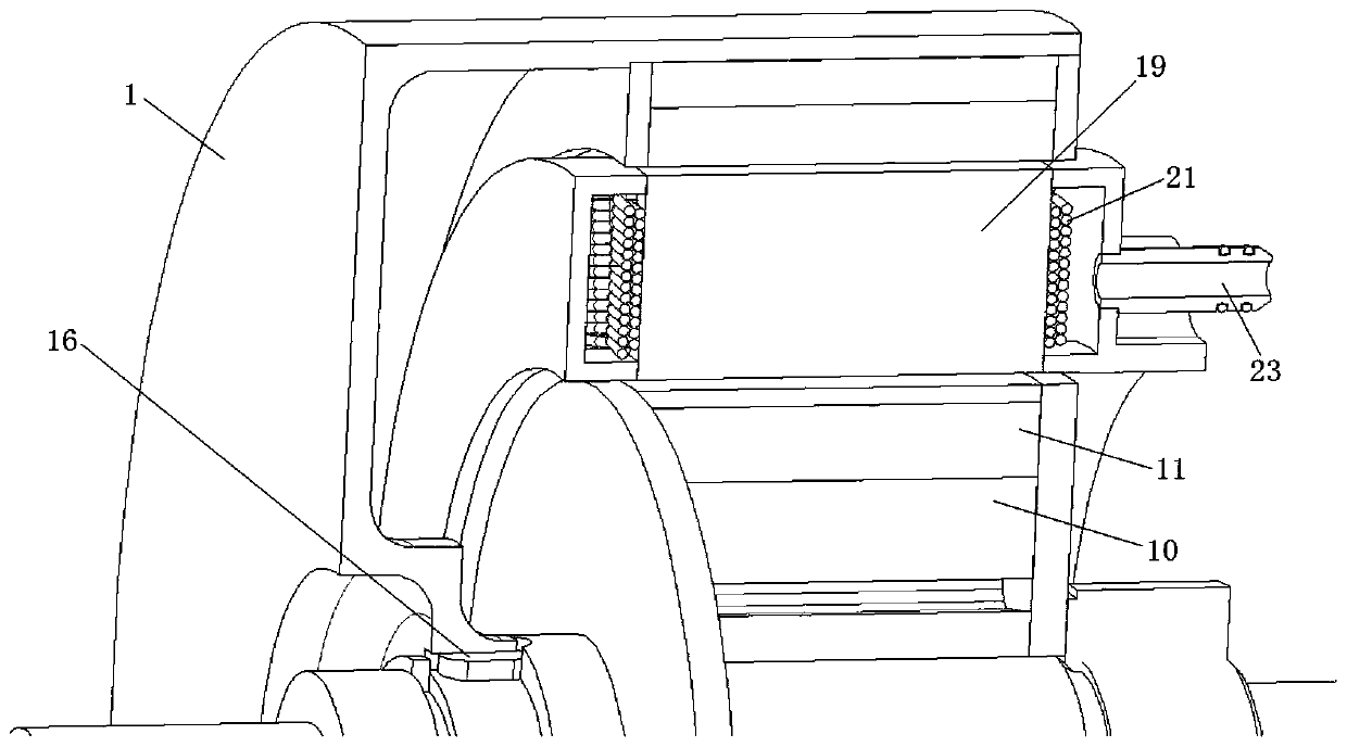
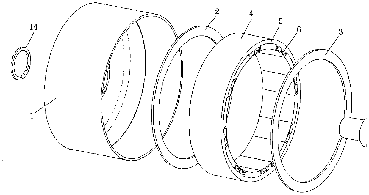
[0027] specific embodiment Figure 1 to Figure 8 As shown, this embodiment includes the outer rotor assembly part, the inner rotor assembly part and the stator assembly part; the outer rotor assembly part includes the outer rotor bracket 1, the outer rotor left end plate 2, the outer rotor right end plate 3, the outer rotor iron Core 4, outer rotor magnetic steel 5, outer rotor magnetic steel assembly hole 6, outer rotor left end plate 2, outer rotor right end plate 3, outer rotor core 4 are all ring-shaped structures, outer rotor left end plate 2, outer rotor iron The core 4 and the right end plate 3 of the outer rotor are arranged in the outer rotor bracket 1 after they are close together in sequence. The outer rotor magnetic steel 5 and the outer rotor magnetic steel assembly holes 6 are arranged on the inner wall surface of the outer rotor iron core 4 at intervals. The outer rotor magnetic steel 5 , Outer rotor magnetic steel mounting holes 6 are arc-shaped. The inner rot...
Embodiment 2
[0031] In Embodiment 1, the longitudinal sections of the oil discharge hole 20 and the intermediate partition 25 are conical structures; in this embodiment, the longitudinal sections of the oil discharge hole 20 and the intermediate partition 25 can be designed as a rectangular structure, that is, the stator The winding 21 becomes a tapered structure.
[0032] In Embodiment 1, the oil inlet pipe 23 and the oil outlet pipe 24 are respectively arranged at the upper and lower ends of the right side wall of the stator winding right outer cover 18; Optimization, as long as the upper part of the oil chamber is connected with the oil inlet pipe 23, and the lower part of the oil chamber is connected with the oil outlet pipe 24.
[0033] In Embodiment 1, the two intermediate partitions 25 are arranged in the middle part of the stator winding right outer cover 18, and there is no restriction on the circumferential distribution angle of the upper and lower oil chambers; according to the ...
PUM
 Abstract
Description
Claims
Application Information
 - R&D Engineer
- R&D Manager
- IP Professional
- Industry Leading Data Capabilities
- Powerful AI technology
- Patent DNA Extraction
Browse by: Latest US Patents, China's latest patents, Technical Efficacy Thesaurus, Application Domain, Technology Topic, Popular Technical Reports.
© 2024 PatSnap. All rights reserved.Legal|Privacy policy|Modern Slavery Act Transparency Statement|Sitemap|About US| Contact US: help@patsnap.com