Efficient Diffusion Process for Selective Emitter Solar Cells

A solar cell and diffusion process technology, applied in the field of solar cells, can solve the problems of low battery Uoc, poor square resistance uniformity, and Isc reduction, and achieve the effects of improved square resistance uniformity, low square resistance, and good metallization contact

Active Publication Date: 2021-05-04
JIANGSU SHUNFENG PHOTOVOLTAIC TECH CO LTD
View PDF10 Cites 0 Cited by
  • Summary
  • Abstract
  • Description
  • Claims
  • Application Information

AI Technical Summary

Problems solved by technology

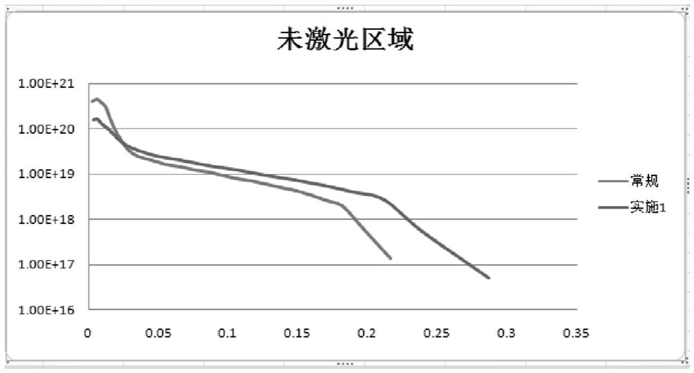
[0004] 1. The surface concentration of shallow laser doping (non-laser area) and laser heavily doped laser area is relatively high, and high surface concentration is more serious for surface recombination, resulting in a relatively low Uoc of the battery
[0005] 2. The uniformity of diffusion resistance prepared by this method is relatively poor, which will lead to a decrease in Isc
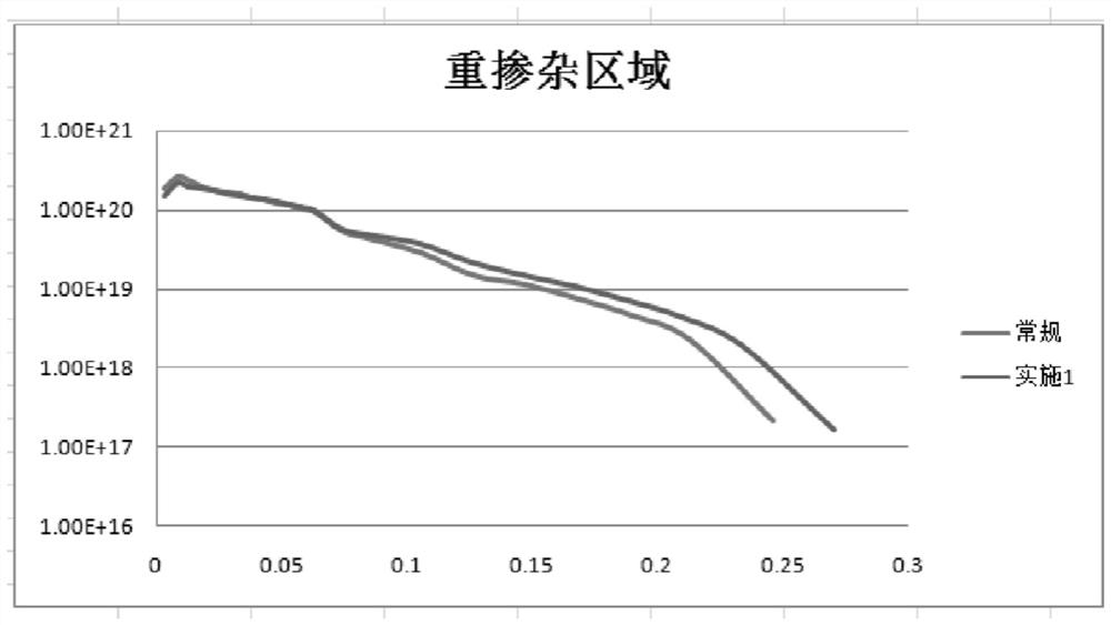
[0006] 3. The current low surface concentration diffusion process is not compatible with the laser doping process. The low surface concentration after diffusion will directly lead to a low phosphorus source content in the phosphosilicate glass, thereby reducing the surface concentration of the laser heavily doped area. Shallow doping Low dopant surface concentration is beneficial to reduce the recombination of the surface and improve the opening voltage of the battery, but the heavily doped region needs to be in contact with the metal electrode, and the low surface concentration will lead to poor contact of the battery and reduce the efficiency of the battery

Method used


Image

  • Efficient Diffusion Process for Selective Emitter Solar Cells
  • Efficient Diffusion Process for Selective Emitter Solar Cells

Examples


Embodiment Construction

[0030]The present invention will now be described in detail with reference to the accompanying drawings and preferred embodiments. These figures are schematic diagrams, which will be described only in a schematic manner, and therefore it only shows the configurations related to the present invention.

[0031]A highly efficient selective emitter solar cell diffusion process, including the following steps:

[0032]1. Entering the boat: Time 500-600S, temperature 750-780 ° C, large nitrogen 2-5SLM;

[0033]2, warmth: time 200-300s, temperature 750-780 ° C, large nitrogen 1-2slm;

[0034]3, constant temperature: time 100-200s, temperature 750-780 ° C, large nitrogen 0.5-1 SLM;

[0035]4, oxidation: time 300-400s, temperature 790-800 ° C, large nitrogen 1-5SLM, oxygen flow 1-2 SLM;

[0036]5, deposition 1: Time 400-600s, temperature 790-800 ° C, large nitrogen 1-5SLM, oxygen flow 0.5-1.5 ° LM, small nitrogen flow 0.5-1.2 SLM;

[0037]6, advance 1: Time 500-800s, temperature 800-830 ° C, large nitrogen 1-5SLM...


PUM


Abstract

The invention relates to a high-efficiency selective emitter solar cell diffusion process, including: boat entry-temperature rise-constant temperature-oxidation-deposition 1-advancement 1-deposition 2-advancement 2-oxidation-deposition 3-heating-cooling-deposition 4‑Cool down‑take the boat. In the present invention, the phosphorus source is activated by increasing the temperature after the high-temperature post-oxidation and low-temperature post-deposition steps, maintaining a certain high temperature, and then cooling down to oxidize and deposit getter-rich phosphorus. This improved step can effectively make the PSG already formed The phosphorus source in PSG can continue to distribute into the silicon matrix, and in addition, PSG is rich in a large amount of effective phosphorus source. The improvement of the process makes the non-laser area continue to maintain a low surface concentration after diffusion, while the laser heavily doped area has a high surface concentration, which effectively solves the compatibility problem between the low surface concentration of the non-laser area and the high surface concentration of the laser heavily doped area; Through the improvement of the process, the uniformity of the square resistance after diffusion has been significantly improved; the square resistance of the laser heavily doped area is lower, and the metallization contact is better.

Description

Technical field[0001]The present invention relates to the field of solar cell technology, in particular, a highly efficient selective emitter solar cell diffusion process.Background technique[0002]At present, the preparation route of the selective emitter PERC solar cell is basically the following path: 1 decrep; 2 diffusion; 3 laser doping; 4 back acid polishing; 5 secondary annealing; 6 back alumina; PE; 8 back laser slot; silk screen printing; ⑩ injection test; where is more critical 3, 4 steps of diffusion process basically adopt high flux diffusion processes, the basic structure of high flux diffusion process is: warming - oxidation - Sedimentary POCI3 - pilot - cooling - out of boat; the high square resistance (120-130) made by this method can basically meet the needs of selective emitter PERC batteries.[0003]However, the battery preparation of this method diffusion process has the following problems:[0004]1. Laser shallow doped (unlike laser region) is high, and the high surf...

Claims


Application Information

Patent Timeline
Patent Type & Authority Patents(China)
IPC IPC(8): H01L31/18H01L21/225H01L31/068
CPCH01L21/2256H01L31/068H01L31/1804Y02E10/547Y02P70/50
Inventor 瞿辉曹玉甲孙玉峰
Owner JIANGSU SHUNFENG PHOTOVOLTAIC TECH CO LTD
Why Eureka
Try Eureka