
Ablation-resistant bimetal combined piston ring, internal combustion engine and sealing method

A piston ring and bimetal technology, applied in the design and manufacture of internal combustion engine parts, can solve the problems of not seriously considering the sealing of the contact surface of the two rings, increasing the wear rate of the piston and cylinder liner, and reducing the service life of the piston ring, etc., to achieve improvement Heat deformation problem, improve lubrication effect, reduce the effect of carbon deposition problem

Pending Publication Date: 2019-08-30
TIANJIN UNIV
View PDF0 Cites 0 Cited by
  • Summary
  • Abstract
  • Description
  • Claims
  • Application Information

AI Technical Summary

Problems solved by technology

[0006] (1) Most of the existing combined piston rings do not seriously consider the sealing problem at the contact surface of the two rings, which causes the airflow to leak through the gap at the contact surface of the two rings, greatly reducing the sealing effect;
[0007] (2) When the piston runs to the upper part of the cylinder liner, it is difficult to lubricate and may be ablated and deformed, which not only increases the resistance, but also increases the wear rate of the piston and cylinder liner, reducing the service life of the piston ring;
[0008] (3) Most of the existing piston rings are single-piece piston rings, and the upper and lower parts are heated differently, which may easily lead to ring deformation and seal failure;
[0009] (4) In order to generate peripheral tension and to expand the piston during installation, a straight-through cut is provided in a part of the circumference, so there are inevitably problems of air leakage and oil leakage at the joint

Method used


Image

  • Ablation-resistant bimetal combined piston ring, internal combustion engine and sealing method
  • Ablation-resistant bimetal combined piston ring, internal combustion engine and sealing method
  • Ablation-resistant bimetal combined piston ring, internal combustion engine and sealing method

Examples


Embodiment Construction

[0041] In order to make the object, technical solution and advantages of the present invention clearer, the present invention will be further described in detail below in conjunction with specific embodiments and with reference to the accompanying drawings.

[0042] Since the position of the product of the present invention can be changed at will, the location words such as "up", "down", "left" and "right" in the present invention only represent relative positional relationships, and are not used to limit absolute positions. location relationship.

[0043] The invention discloses an ablation-resistant bimetal combined piston ring, an internal combustion engine and a sealing method, which mainly solve the problem of mechanical deformation of the piston ring and the indirect air leakage problem, specifically including deformation of the ring due to uneven heating of the upper and lower ring surfaces ; The inherent air leakage problem of the piston ring of the internal combustion...


PUM


Abstract

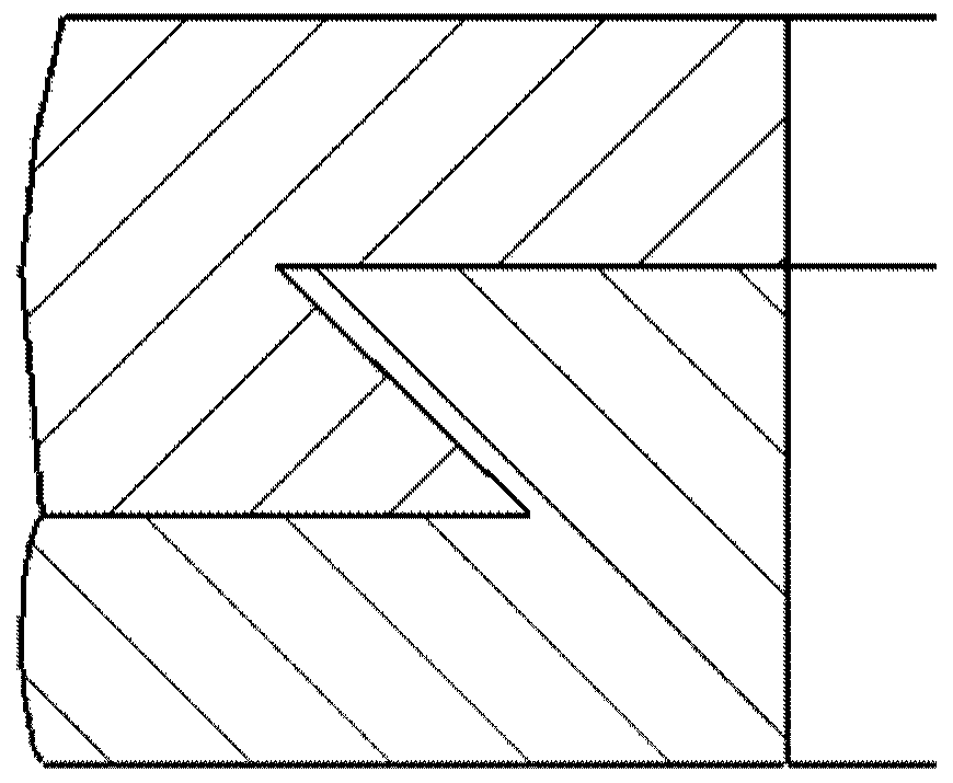
The invention discloses a bimetal combined piston ring, an internal combustion engine adopting same and a piston sealing method. Specifically, the bimetal combined piston ring comprises a metal firstpiston ring and a metal second piston ring; the cross section of a main body of the first piston ring is stepped; the stepped surface is positioned on the inner circumferential side of the first piston ring; the inner circumferential surface of the lower section of a step is a conical surface inclined inwards towards the vertical surface of the step by 15-75 DEG; the cross section of a main body of the second piston ring is stepped; the stepped surface is positioned on the outer circumferential side of the second piston ring; and the outer circumferential surface of an upper section of the step is an outer inclined conical surface complementary to the cone angle of the inner inclined conical surface of the first piston ring. By applying the piston ring, the dynamic property of the internalcombustion engine can be improved, and meanwhile, the wear rate of the piston ring is reduced, so that the service life of the ring is prolonged.

Description

technical field [0001] The invention relates to the field of design and manufacture of internal combustion engine parts, in particular to an ablation-resistant bimetal combined piston ring, an internal combustion engine and a sealing method. Background technique [0002] The piston ring is an important part in the combustion chamber of an internal combustion engine. It is an elastic metal ring assembled inside the piston ring groove. Through its own elastic force and the pressure of the gas in the cylinder, a seal is formed between the outer circle of the cylinder wall and the surface of the piston ring groove. , is the core component of the internal combustion engine combustion chamber. At present, there are mainly two types of piston rings: single type and combined type. Usually need to install 3-4 piston rings on a piston. [0003] The main functions of the piston ring mainly include the four major functions of sealing, oil control, heat transfer and support, which dire...

Claims


Application Information

Patent Timeline
IPC IPC(8): F16J9/20F16J9/16F16J9/26
CPCF16J9/20F16J9/16F16J9/26
Inventor 梁兴雨王诗文舒歌群卫海桥田华王月森
Owner TIANJIN UNIV
Learn More