
Auxiliary energy supply system of fuel cell car

A fuel cell and vehicle auxiliary technology, applied in electric vehicles, battery/fuel cell control devices, power management, etc., can solve problems such as energy waste, low energy utilization rate of the vehicle, and insufficient energy of the lithium battery itself

Active Publication Date: 2019-08-30
BEIHANG UNIV
View PDF5 Cites 9 Cited by
  • Summary
  • Abstract
  • Description
  • Claims
  • Application Information

AI Technical Summary

Problems solved by technology

[0006] The present invention aims at problems such as large energy waste caused by the ineffective use of energy in the hydrogen depressurization process of the fuel cell vehicle in the prior art, low energy utilization rate of the whole vehicle, insufficient energy of the lithium battery itself and lack of energy supplement under some working conditions, etc., and provides An auxiliary energy supply system for fuel cell vehicles, which makes full use of the original components of electric vehicles and innovatively combines the recovery and utilization of high-pressure hydrogen pressure relief energy with lithium battery charging after simply and cleverly adding a few components. While improving the overall energy utilization rate of the fuel cell, it also effectively supplements the energy of the lithium battery, improving the overall economy of the fuel cell vehicle, simple, efficient and convenient

Method used


Image

  • Auxiliary energy supply system of fuel cell car
  • Auxiliary energy supply system of fuel cell car
  • Auxiliary energy supply system of fuel cell car

Examples


Embodiment Construction

[0021] The present invention will be further described in detail below in conjunction with the accompanying drawings.

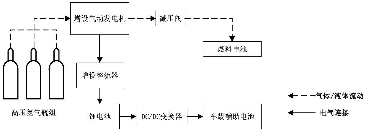
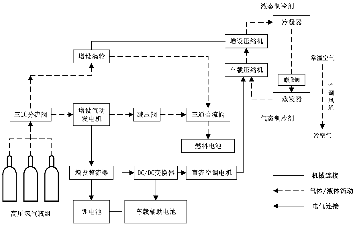
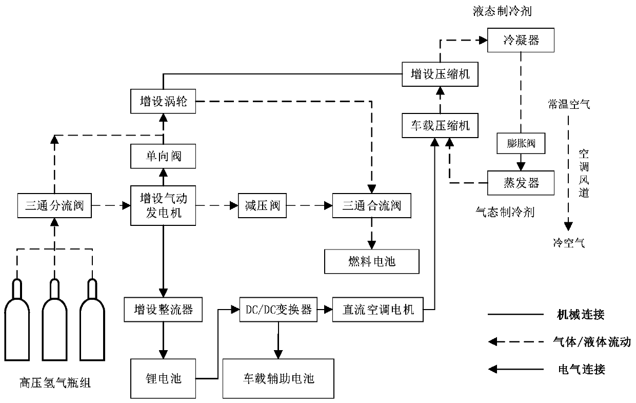
[0022]The invention relates to an auxiliary energy supply system for fuel cell vehicles, which is applied to fuel cell vehicles (including fuel cell non-electric vehicles and fuel cell electric vehicles), such as figure 1 As shown in the schematic diagram of the first preferred structure of the present invention, it includes the high-pressure hydrogen cylinder set of the automobile battery system itself, the pressure reducing valve, the fuel cell, and the lithium battery, DC / DC converter, and vehicle-mounted auxiliary battery that are electrically connected in sequence, and also includes an additional Pneumatic generators, additional rectifiers, additional pneumatic generators and pressure reducing valves are sequentially arranged on the airflow path between the high-pressure hydrogen cylinder group and the fuel cell (the airflow path is shown by the dotted ar...


PUM


Abstract

The invention relates to an auxiliary energy supply system of a fuel cell car. The auxiliary energy supply system comprises original components of the car, and further comprises an additionally arranged pneumatic power generator and an additionally arranged rectifier, wherein the additionally arranged pneumatic power generator and a pressure reducing valve are sequentially arranged on a gas path between a high-pressure hydrogen cylinder group and a fuel cell, the additionally arranged rectifier is arranged between the additionally arranged pneumatic power generator and a lithium battery, the additionally arranged pneumatic power generator is driven through pressure relief energy of high-pressure hydrogen in the high-pressure hydrogen cylinder group so as to generate electric energy, meanwhile, hydrogen gas passing through the additionally arranged pneumatic power generator enters the fuel cell through the pressure reducing valve, the additionally arranged rectifier receives the electric energy of the additionally arranged pneumatic power generator to carry out rectification, and then assists in lithium battery charging, and the lithium battery supplements electric energy for a vehicle-mounted auxiliary battery through a DC / DC converter. The system effectively solves the problems that in the prior art, a fuel cell car is large in energy waste, and low in energy utilization rateof the whole vehicle, the energy of a lithium battery is insufficient under the partial working conditions, and energy supplement is lacked, and the overall energy utilization rate is improved.

Description

technical field [0001] The invention relates to the technical field of energy recovery and utilization, in particular to an auxiliary energy supply system for a fuel cell vehicle. Background technique [0002] As the global greenhouse effect becomes more and more serious, as the consumption of fossil fuels increases day by day, and as environmental issues are paid more and more attention, the country begins to vigorously develop clean energy and new energy vehicles. New energy vehicles use electric energy instead of fossil fuels such as petroleum as power, get rid of dependence on petroleum and reduce environmental pollution at the same time, which is an efficient solution for green transportation. Compared with traditional fuel-consuming vehicles, vehicles powered by hydrogen fuel cells have advantages such as high energy conversion efficiency of fuel cells, environmental protection, no vibration, low noise, long life, more raw materials for hydrogen production, and fast en...

Claims


Application Information

Patent Timeline
IPC IPC(8): B60L58/30B60H1/00
CPCB60H1/00392B60H1/00428B60L58/30Y02T10/72Y02T10/88Y02T90/40
Inventor 杨世春华旸金鑫娜潘宇巍闫啸宇
Owner BEIHANG UNIV
Learn More