Emergency stop control method and system for robot

A control method and robot technology, applied in the field of robot control, can solve the problems of impact force evaluation without emergency stop, damage to the structure of the reducer, moving arm, and no reasonable interaction of the servo system, and achieve the effect of high cost performance and high integration.

Active Publication Date: 2019-08-30
CHENGDU CRP ROBOT TECH CO LTD
View PDF9 Cites 4 Cited by
  • Summary
  • Abstract
  • Description
  • Claims
  • Application Information

AI Technical Summary

Problems solved by technology

[0003] The purpose of the present invention is to provide an emergency stop control method and system for robots, which is used to solve the problem of insufficient emergency stop security in the prior art, the lack of reasonable interaction between the servo and the system, and the impact of the emergency stop on the robot body. Force evaluation, under high-speed conditions without reasonable treatment to stop forcibly, resulting in structural damage to the reducer and moving arm, and seriously shortening the service life of the robot body

Method used


Image

  • Emergency stop control method and system for robot
  • Emergency stop control method and system for robot
  • Emergency stop control method and system for robot

Examples


Embodiment 1

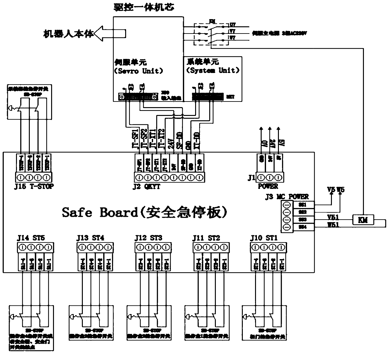
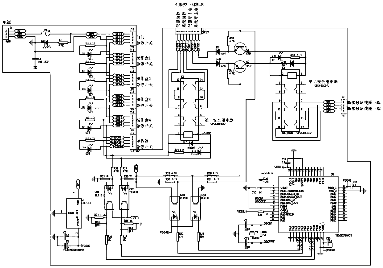
[0050] combined with figure 1 and figure 2As shown, an emergency stop control method for a robot, including:

[0051] A: The emergency stop switch of the external operation box (the safety emergency stop board can be connected to the emergency stop switch of the cabinet door, the emergency stop switch of the 4 external operation boxes and the teaching pendant) is used as a direct operating element, and the emergency stop switch adopts a double contact Normally closed contacts, the first pair of normally closed contacts is connected to the 24V terminal of the safety emergency stop board, and the second pair of normally closed contacts is connected to the GND of the safety emergency stop board. Terminal connected to the coil of the first safety relay of the safety emergency stop board and turned on; the double contact output of the emergency stop switch is output to the 24V end and GND end of the safety emergency stop board: the first safety relay is not connected when there i...

Embodiment 2

[0058] On the basis of Example 1, the emergency stop impulse time and deceleration parameters adopt the trapezoidal deceleration method to make the six axes decelerate and stop at the same time. The specific calculation method is:

[0059] (1) Calculate the emergency stop momentum time t dcc

[0060] Impulse time from emergency stop t dcc equal to the joint angular velocity divided by the joint angular acceleration get

[0061]

[0062] During the deceleration process, the joint torque τ of the reducer is less than or equal to the allowable torque value τ of acceleration and deceleration gdcc ,

[0063] get

[0064] τgdcc (2)

[0065] According to the Lagrangian dynamics formula, we get

[0066]

[0067] in, is the inertial force, is the centrifugal force and the Coriolis force, G(Θ) is the gravity part, M(Θ) is the moment of inertia matrix, is the relevant parts such as centrifugal force and Coriolis force, Θ is the joint angle, is the joint angular v...

Embodiment 3

[0078] combined with figure 1 And attached figure 2 As shown, a kind of emergency stop control system for the robot, including emergency stop switch, safety emergency stop board, drive and control integrated core, contactor and main power supply connected in sequence, also includes for the described safety emergency stop board and emergency stop switch power supply module, where:

[0079] The emergency stop switch includes a plurality of emergency stop buttons installed in the external operation box, and the emergency stop buttons are respectively connected to the safety emergency stop board;

[0080] The safety emergency stop board includes a first safety relay, a second safety relay and an ARM unit, and the first safety relay is respectively connected to the emergency stop switch and the drive-control integrated movement for receiving the emergency stop signal of the emergency stop switch and transmitted to the drive-control integrated core; the second safety relay is res...


PUM


Abstract

The invention discloses an emergency stop control method for a robot. The emergency stop control method comprises the steps that when an emergency stop switch is pressed, a safety emergency stop boardreceives an emergency stop signal and sends the emergency stop signal to a drive and control integrated machine core, and timing is started; the drive and control integrated machine core calculates emergency stop impact force time and deceleration speed parameters, and deceleration is started; and when deceleration is completed or the time is up, the drive and control integrated machine core disconnects a servo main power supply signal of the safety emergency stop board, and the safety emergency stop board cuts off a servo main power supply of the drive and control integrated machine core. The invention also discloses an emergency stop control system for the robot. The system comprises the emergency stop switch, the safety emergency stop board, the drive and control integrated machine core, a contactor and the main power supply which are connected in sequence. Deceleration and stopping are carried out at the highest speed under the condition that the service life of a body speed reducer and arms is not shortened, so that the safety of the robot during emergency stop is improved, and it is guaranteed that the body speed reducer and the movement arms are not damaged during emergencystop of the robot.

Description

technical field [0001] The invention relates to the technical field of robot control, in particular to an emergency stop control method and system for a robot. Background technique [0002] The industrial robot control cabinet is a complete set of system equipment that can control and drive the industrial robot body to operate in the industrial environment according to the programmed and preset trajectory. At present, the safety of domestic robots needs to be improved, which is reflected in: after pressing the emergency stop or detecting a fault by itself, it does not stop through independent, multiple redundant, hardware methods, or the safety level of emergency stop is not enough; There is no reasonable interaction with the system, no evaluation of the impact force of the emergency stop of the robot body, and no reasonable handling at high speed to force the stop, resulting in structural damage to the reducer and the moving arm, which seriously shortens the service life of...

Claims


Application Information

Patent Timeline
Patent Type & Authority Applications(China)
IPC IPC(8): B25J9/16B25J19/06
CPCB25J9/16B25J19/06
Inventor 郭忠波徐纯科杨金桥夏辉胜朱路生
Owner CHENGDU CRP ROBOT TECH CO LTD
Why Eureka
Try Eureka