RFSoC-based SAR imaging real-time signal processing device

A technology of real-time signal and processing device, applied in the field of communication, can solve the problems of increasing design difficulty, low real-time performance, complicated system structure, etc., and achieves the effect of increasing design difficulty, reducing design difficulty and simple circuit structure

Pending Publication Date: 2019-08-27
XIDIAN UNIV
View PDF8 Cites 4 Cited by
  • Summary
  • Abstract
  • Description
  • Claims
  • Application Information

AI Technical Summary

Problems solved by technology

The disadvantage of this system is that the system uses a multi-chip structure of an analog-to-digital converter chip + a programmable logic gate array device FPGA chip + multiple digital signal processor DSP chips, which leads to a complicated system structure and a large volume. It is too large to achieve miniaturization; secondly, the system uses the Ethernet physical layer PHY chip W5300 at a rate of 100M, which cannot achieve a higher rate of Gigabit Ethernet, resulting in lower real-time performance of the system
The disadvantages of this system are that, firstly, the programmable logic gate array device FPGA is connected at high speed with the multi-channel SRIO adopted by the multi-chip digital signal processor DSP, and it is vulnerable to external interference when transmitting data, resulting in bit errors; secondly, the analog-to-digital conversion The ADS54J66 chip of the device works at the highest sampling rate of 500Msps, and the data link rate of the JESD204B communication protocol with the FPGA is 10Gbps, resulting in a large power consumption of the field programmable logic gate array FPGA device, resulting in low stability of the device; finally , the digital-to-analog conversion ADS54J66 chip used in this system has a low sampling rate and cannot directly sample the radio frequency. It needs to introduce an analog down-conversion circuit and an analog filter circuit before it can be used, which increases the difficulty of design.

Method used


Image

  • RFSoC-based SAR imaging real-time signal processing device
  • RFSoC-based SAR imaging real-time signal processing device
  • RFSoC-based SAR imaging real-time signal processing device

Examples


Embodiment Construction

[0017] The present invention will be further described below in conjunction with the accompanying drawings.

[0018] Reference attached figure 1 , to further describe the overall circuit of the present invention,

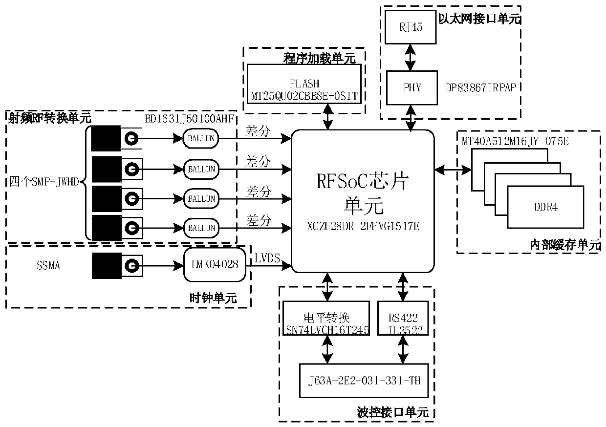
[0019] The overall circuit of the present invention includes a radio frequency RF conversion unit, a clock unit, a program loading unit, an Ethernet interface unit, an internal buffer unit, a wave control interface unit, and a radio frequency system on chip RFSoC chip unit.

[0020] In an embodiment of the present invention, the radio frequency RF conversion unit is connected to the radio frequency system-on-chip RFSoC chip unit through a differential interface, and the output interface of the radio frequency RF conversion unit has four differential interfaces, and the RFSoC chip unit of the radio frequency system-on-chip The differential interface is the analog-to-digital conversion resource sampling interface of the chip, and the output interface of the RF conver...


PUM


Abstract

The invention discloses an RFSoC-based SAR imaging real-time signal processing device. The device comprises an RF conversion unit, a clock unit, a program loading unit, an Ethernet interface unit, aninternal cache unit, a wave control interface unit and an RFSoC unit. The RF conversion unit is connected with the RFSoC unit through a differential interface; the clock unit is connected with the RFSoC unit through a low-voltage differential interface; the program loading unit is connected with the RFSoC unit through a bus interface; the Ethernet interface unit is connected with the RFSoC unit through a link port; the internal cache unit is connected with the RFSoC unit through a bus interface; and the wave control interface unit is connected with the RFSoC unit through a serial interface anda bus interface. The device has the advantages of being small in size, high in sampling rate, high in reliability, low in power consumption and high in stability.

Description

technical field [0001] The invention belongs to the technical field of communication, and further relates to a device for real-time signal processing of synthetic aperture radar SAR (Synthetic aperture radar) imaging based on an RFSoC (Radio Frequency System on Chip) chip in the technical field of radar digital signal processing. The present invention can be used to directly receive the radio frequency signal output by the radar antenna assembly, and complete the processing of analog-to-digital conversion, digital down-conversion, pulse compression, and real-time imaging on the single-chip radio frequency system-on-chip RFSoC chip. The interface outputs imaging result data. Background technique [0002] The RF SoC chip is a series of Zynq UltraScale+RFSoC chips from Xilinx, which integrates RF (Radio Frequency) data converters, SD-FEC cores, high-performance UltraScale+ programmable logic and multi-core ARM processing. system. Traditional RF digital signal conditioning and...

Claims


Application Information

Patent Timeline
Patent Type & Authority Applications(China)
IPC IPC(8): G01S13/90G01S7/41
CPCG01S13/90G01S7/41G01S13/9004
Inventor 全英汇陈广雷刘欢马宝洋章振栋杜潇剑姚洪彬隋尚兼安子建吴玲清赵佳琪吴彬彬
Owner XIDIAN UNIV
Why Eureka
Try Eureka