Thermal fiber grating wind speed and wind direction sensor and detection method
A fiber grating, wind speed and wind direction technology is applied in the direction of measuring fluid speed by using thermal variables, which can solve the problems of poor antimagnetic effect and short life, and achieve the effects of prolonging service life, low loss, improving applicability and stability
- Summary
- Abstract
- Description
- Claims
- Application Information
AI Technical Summary
Problems solved by technology
Method used
Image

Examples
Embodiment 1
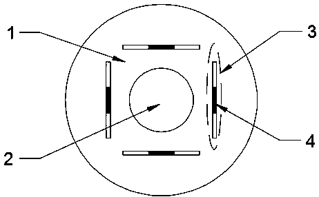
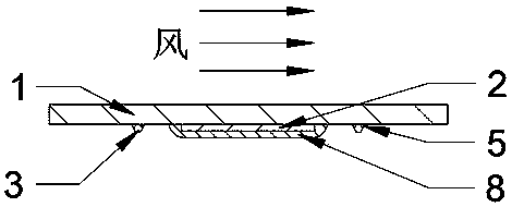
[0036] combine figure 1 and figure 2 Describe Embodiment 1 of the present invention: a thermal fiber grating wind speed and wind direction sensor, including: a substrate 1, a heating resistance wire 2 sprayed on the substrate 1, and an orthogonal arrangement bonded to the substrate 1 Four fiber grating temperature sensors 3 around the heating resistance wire 2 are characterized in that the heating resistance wire 2 is arranged in a spiral shape, and welding joints 9 are left at both ends; the sensing element of the temperature sensor is a fiber Bragg grating .
[0037] In Embodiment 1, the fiber grating temperature sensor 3 , the heating resistance wire 2 and the thin sheath 6 are located on the leeward side of the substrate 1 .
[0038] In Embodiment 1, the substrate 1 is one or more of monocrystalline silicon, silicide, glass, and ceramics stacked in different orders; the thickness of the substrate 1 is 0.1-2.0 mm.
[0039] In Embodiment 1, the heating resistance wire 2 ...
Embodiment 2
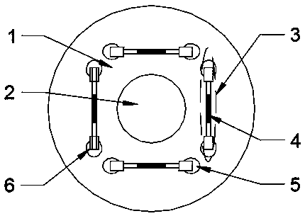
[0046]combine image 3 and Figure 4 Embodiment 2 of the present invention is described: a kind of thermal fiber grating wind speed and wind direction sensor, its structure has been improved in above-mentioned embodiment, described fiber grating temperature sensor 3, heating resistance wire 2 and fine sleeve 6 are positioned at substrate 1 windward side; the optical fiber temperature sensor 3 is placed in the thin sleeve 6, and the thin sleeve 6 is fixed on the substrate 1 by bonding.
[0047] In Embodiment 2, the optical fiber temperature sensor 3 is entirely placed in a thin sleeve 6 and fixed on one side. The diameter of the thin sleeve 6 is 0.5-5mm; the material of the thin sleeve 6 is ceramics, stainless steel, glass, plastic, Aluminum, iron, copper and their alloys.
[0048] In embodiment 2, there is a resistance wire protection layer 7 on the surface of the heating resistance wire. The glass frit is heated to a liquid state in an environment of 400° C., and the heati...
Embodiment approach
[0049] The present invention also provides an embodiment: a method for measuring a thermal fiber grating wind speed and direction sensor, comprising the following steps:
[0050] Step 100: In a windless environment, perform a calibration measurement and record the center drift value of the fiber grating;
[0051] Step 200: Under the environment to be tested, perform detection and measurement, and record the center wavelength drift value of the fiber grating;
[0052] Step 300: Using the calibration measurement value as a reference, perform data processing on the detected FBG center wavelength drift value to obtain the wind direction and wind speed of the measurement environment.
[0053] In an embodiment, the specific process of the calibration measurement described in step 100: the heating resistance wire is heated by an AC signal with a power of 0.1-1W, and at the same time, the heating resistance wire conducts heat conduction heating on the fiber grating temperature sensor ...
PUM
| Property | Measurement | Unit |
|---|---|---|
| Length | aaaaa | aaaaa |
Abstract
Description
Claims
Application Information
 - R&D
- Intellectual Property
- Life Sciences
- Materials
- Tech Scout
- Unparalleled Data Quality
- Higher Quality Content
- 60% Fewer Hallucinations
Browse by: Latest US Patents, China's latest patents, Technical Efficacy Thesaurus, Application Domain, Technology Topic, Popular Technical Reports.
© 2025 PatSnap. All rights reserved.Legal|Privacy policy|Modern Slavery Act Transparency Statement|Sitemap|About US| Contact US: help@patsnap.com