Electro-hydraulic regulating and controlling device for valve timing

A valve timing and control device technology, which is applied in the direction of valve devices, engine components, machines/engines, etc., can solve the problem of limited improvement in engine power, fuel economy and emission reduction, and can not better meet the requirements of engine gas distribution. Requirements, can not better meet the engine gas distribution requirements and other issues, to achieve good dynamic response characteristics, simple structure, high integration effect

Pending Publication Date: 2019-08-23
GUIZHOU UNIV
View PDF0 Cites 1 Cited by
  • Summary
  • Abstract
  • Description
  • Claims
  • Application Information

AI Technical Summary

Problems solved by technology

At present, the variable valve timing adjustment methods mainly include the following types: 1) Each valve corresponds to a cam group composed of multiple different cams, and different cams are used to control the movement of the valves according to different engine speeds to achieve valve timing adjustment , therefore, this method can only enable the engine to obtain the best valve timing corresponding to the speed of each cam profile in the cam set, and cannot realize the stepless adjustment of valve timing; 2) By changing the relationship between the valve camshaft and the engine crankshaft The relative angle between them realizes the adjustment of the valve timing. Since the continuous angle of the valve opening remains unchanged, this adjustment method has the same angle as increasing the valve advance angle and reducing the valve lag angle at the same time; on the contrary, increasing The valve lag angle must reduce the valve advance angle by the same angle
Therefore, this adjustment method cannot meet the adjustment requirements of the valve advance angle and the valve lag angle under different engine operating conditions at the same time.
3) Electromagnetic direct drive valve, this technology is flexible to adjust, but poor high-speed response, high energy consumption, and large impact, so that this technology cannot better meet the gas distribution requirements of high-speed engines
To sum up, the existing variable valve timing adjustment system can not better meet the gas distribution requirements of the engine at different speeds, so the improvement of the engine's power performance, fuel economy and emission reduction is limited.

Method used


Image

  • Electro-hydraulic regulating and controlling device for valve timing
  • Electro-hydraulic regulating and controlling device for valve timing
  • Electro-hydraulic regulating and controlling device for valve timing

Examples


Embodiment Construction

[0026] The following will clearly and completely describe the technical solutions in the embodiments of the present invention with reference to the accompanying drawings in the embodiments of the present invention. Obviously, the described embodiments are only some, not all, embodiments of the present invention. Based on the embodiments of the present invention, all other embodiments obtained by persons of ordinary skill in the art without making creative efforts belong to the protection scope of the present invention.

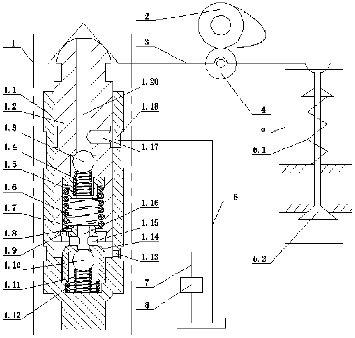
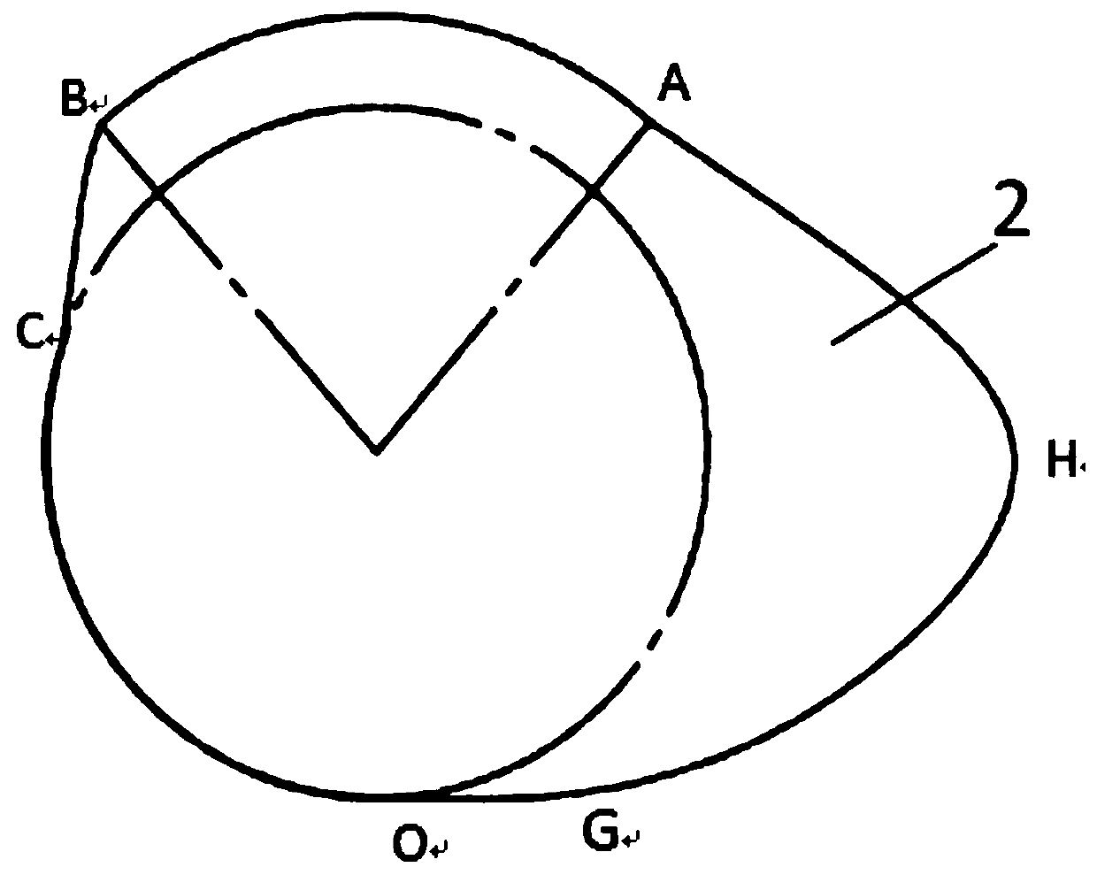
[0027] see Figure 1-4, the present invention provides a technical solution: a valve timing hydraulic control device, including a hydraulic tappet 1, a gas distribution cam 2, a rocker arm 3, a rocker arm roller 4, a valve assembly 5, a lubricating oil circuit 6, a return Oil circuit 7 and solenoid valve 8. Among them: hydraulic tappet 1 includes tappet cover 1.1, tappet 1.2, tappet one-way valve core 1.3, tappet one-way valve spring 1.4, tappet one-way valve...


PUM


Abstract

The invention discloses a hydraulic regulating and controlling device for valve timing. The regulating and controlling device comprises a hydraulic tappet, a valve cam, a rocker arm, a rocker arm running pulley, a valve assembly, a lubricating oil path, an oil returning path and an electromagnetic valve, and the valve assembly comprises a valve spring and a valve. According to the regulating and controlling device, the structure is simple, and the integration level is high; the independent adjustment of an advance angle and a lag angle of the valve can be realized by changing the on-off time of the electromagnetic valve according to the different working conditions of an engine, so that the engine can obtain the optimal advance angle and lag angle of the valve under different working conditions, and the valve timing requirements of the engine under different working conditions can be met; independent and accurate adjustment of the advance angle and the lag angle of the valve can be realized in one cycle; the adjusting range of the lag angle is large, the efficiency of the engine is improved, the power performance is improved, and energy conservation and emission reduction are achieved; when the regulating and controlling device is used for an exhaust valve, the coefficient of residual waste gas in a cylinder can be regulated and controlled in real time, the HCCI combustion modecan be easily realized, the system operation is stable; and during valve closing, the movement processes are same, the seating speeds are same, the movement processes and the seating speeds do not change along with the changing of the rotating speeds of the engine, and the valve seating impact is small.

Description

technical field [0001] The invention relates to the technical field of engines, in particular to an electro-hydraulic control device for valve timing. Background technique [0002] At present, in the cam-driven gas distribution system with hydraulic tappets, the hydraulic tappets are used to automatically compensate the gap caused by the size change of the valve and transmission system due to thermal expansion, manufacturing errors and wear, etc., reduce the impact and improve Sporty smoothness, but no valve-timing adjustments. [0003] Variable valve timing technology can adjust the valve timing parameters according to the actual working conditions of the engine to meet the gas distribution requirements of different working conditions, thereby improving engine power characteristics, improving fuel economy and reducing harmful gas emissions. At present, the variable valve timing adjustment methods mainly include the following types: 1) Each valve corresponds to a cam group ...

Claims


Application Information

Patent Timeline
Patent Type & Authority Applications(China)
IPC IPC(8): F01L1/14F01L1/34F01L1/46
CPCF01L1/14F01L1/34F01L1/46
Inventor 陈家兑王自勤田丰果
Owner GUIZHOU UNIV
Why Eureka
Try Eureka