
A main keel welding equipment and welding method

A welding equipment and welding method technology, applied in welding equipment, metal processing equipment, manufacturing tools, etc., can solve the problems of large footprint and low efficiency, achieve small footprint, easy large-scale industrialization, and improve welding The effect of work efficiency

Active Publication Date: 2022-02-18
江苏景枫投资控股集团有限公司
View PDF0 Cites 0 Cited by
  • Summary
  • Abstract
  • Description
  • Claims
  • Application Information

AI Technical Summary

Problems solved by technology

This method is inefficient and occupies a large area

Method used


Image

  • A main keel welding equipment and welding method

Examples


Embodiment Construction

[0039] The technical solution of the present invention will be described in detail below in conjunction with the accompanying drawings.

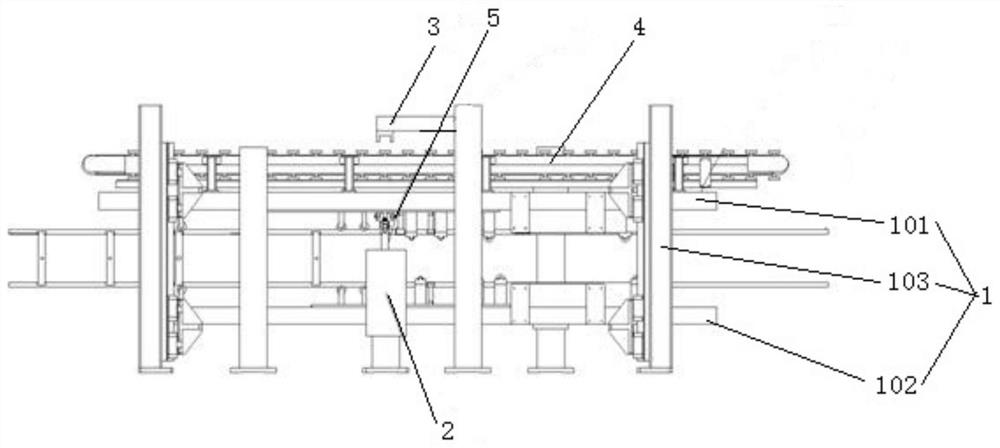
[0040] Such as figure 1 As shown, a main keel welding equipment provided by an embodiment of the present invention includes a frame 1 and a welding device 2 . The welding device 2 is used for welding the main keels, that is, welding the stiffening sheet between the two main keels, so that the two main keels are integrated. The welding device 2 is arranged opposite to the frame 1 . The welding device 2 can be connected with the frame 1, or can be set independently without being connected with the frame 1. When in use, the main keels to be welded are located in the frame 1 and arranged vertically. The vertical arrangement of main keels to be welded refers to the arrangement of two or more main keels up and down.

[0041] Using the main keel welding equipment of the above embodiment, the main keel is placed in the frame 1 . The main keel t...


PUM


Abstract

The invention discloses a main keel welding equipment and a welding method to improve operation efficiency and realize large-scale production. The main keel welding equipment includes a frame and a welding device, and the welding device is arranged opposite to the frame; when in use, the main keels to be welded are located in the frame and arranged vertically.

Description

technical field [0001] The invention belongs to the field of main keel welding, and in particular relates to a main keel welding equipment and a welding method. Background technique [0002] Assembling cold-formed thin-walled steel into a frame structure at the construction site, and then pouring concrete after combining with prefabricated composite panels is a new type of building system with a wide range of applications. The cold-formed thin-walled steel frame adopts a pair of C-shaped cold-formed thin-walled steels connected by stiffeners to form the main keel. Generally, the C-shaped cold-formed thin-walled steel is fixed by drilling screws between the stiffeners, all of which are manually tightened by self-tapping screws. This connection method requires laying a pair of C-shaped cold-formed thin-walled steel on the ground, and then placing the stiffener on the two C-shaped cold-formed thin-walled steels, and then connecting them manually by self-tapping screws. Stiffe...

Claims


Application Information

Patent Timeline
Patent Type & Authority Patents(China)
IPC IPC(8): B23K31/02
CPCB23K31/02
Inventor 不公告发明人
Owner 江苏景枫投资控股集团有限公司
Learn More