


Quick Research
Generate reliable direction feasibility study reports for your R&D in just a few steps.

Technical Q&A
Discover and master advanced knowledge NOW. Basics, ideas, possibilities, all at once.

Find Solutions
As an expert in R&D theories, this can generate solutions to your technical problems instantly.

Evaluate Feasibility
Analyze your overall solution with one click, know your potential R&D risks in advance.

Monitor Landscape
Get weekly tech updates, stay abreast of the latest tech innovations and key insights.
Bag dust removal device for thermal power plant
- Summary
- Abstract
- Description
- Claims
- Application Information
AI Technical Summary
Problems solved by technology
Method used
Image

Examples
Embodiment 1
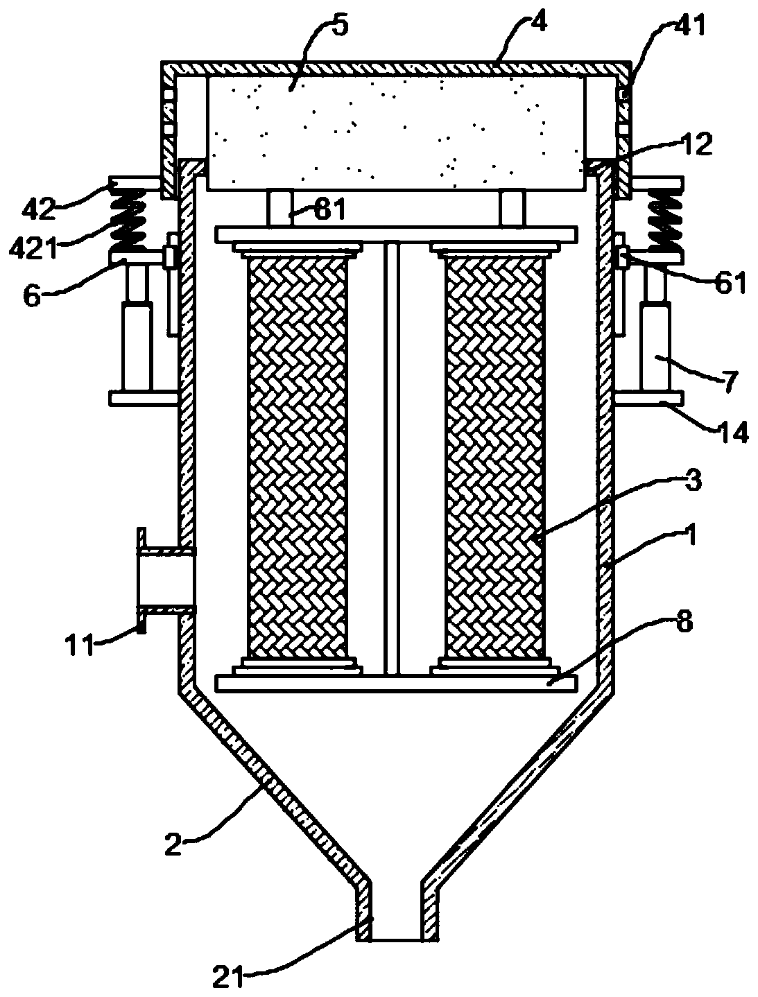
[0021] see Figure 1~2 , in an embodiment of the present invention, a bag-type dedusting device for a thermal power plant includes a dust-removing box 1 and an ash hopper 2; ; The ash hopper 2 is connected to the bottom of the dust removal box 1, and the ash hopper 2 is provided with a dust outlet 21;
[0022] The top of the dust removal box 1 is provided with a movable cover 4, and the movable cover 4 covers the dust removal box 1 inside, and the top of the dust removal box 1 is provided with a perforation 12; the movable cover 4 is provided with an air outlet 41, and the movable cover 4 A plugging block 5 adapted to the perforation 12 is installed on the inner top surface of the inner top surface, so that when the plugging block 5 is disengaged from the air outlet 41, the gas in the dust removal box 1 enters the movable cover 4 through the perforation 12, and then Discharge from air outlet 41 again; On the outer wall of described movable cover 4, connecting plate 42 is fixe...
Embodiment 2
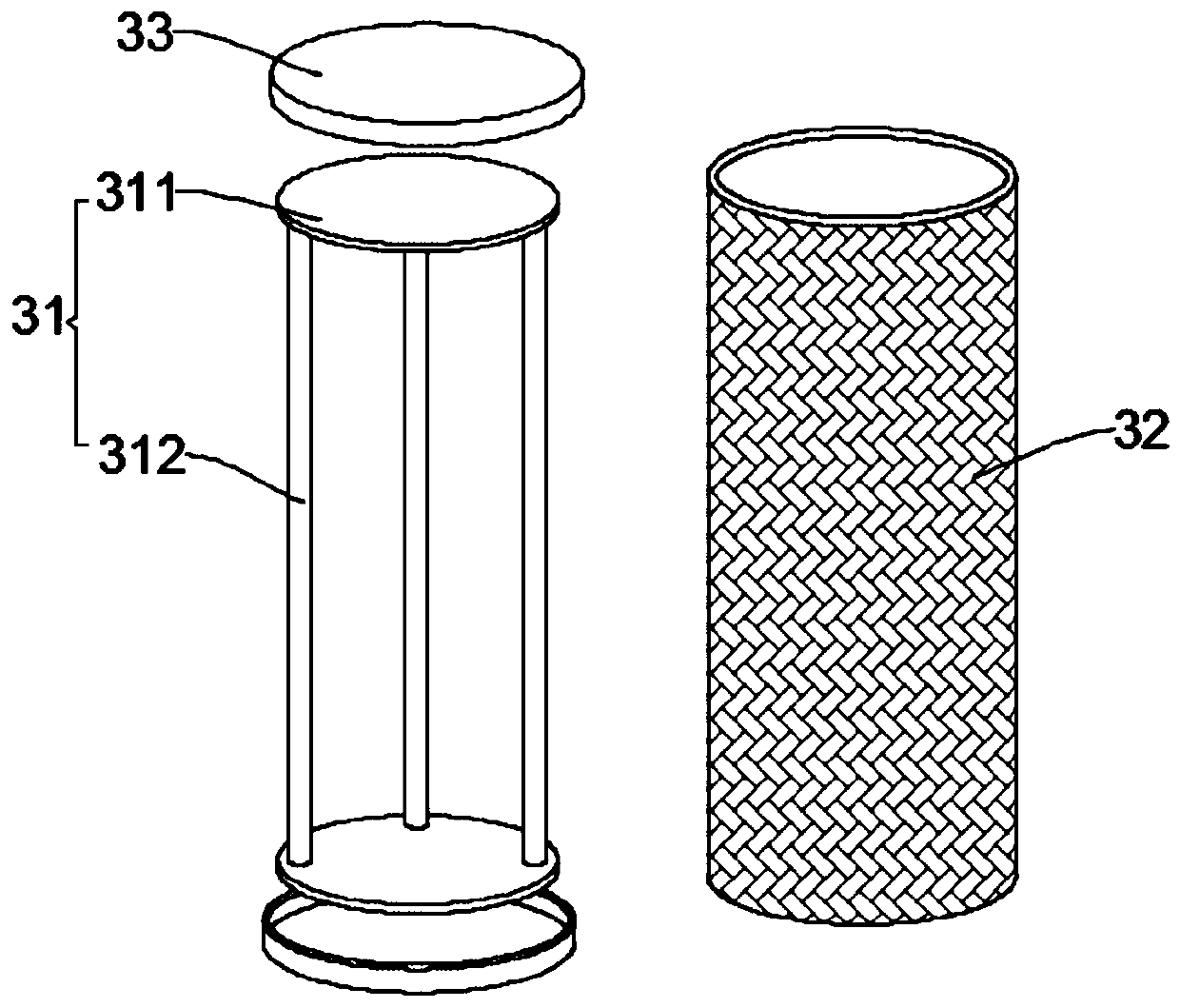
[0030] see image 3 , the embodiment of the present invention mainly improves the bag assembly to a certain extent, specifically:
[0031] The bag assembly 3 includes a bag main body 33, a bracket 31 for supporting the bag main body 33, and a cover plate 32 fastened with the bracket 31; A plurality of vertical rods 312 are fixed equidistantly along the circumferential direction; the cover plate 32 is connected to the base plate 311 through a magnetic attraction. The cover plate 32 is buckled on the base plate 311 by the magnetic attraction between them, thereby fixing the bag main body 33, and when the bag needs to be cleaned, the cover plate 32 only needs to be removed, and then the bag main body 33 can be taken off. , the operation is simple and quick.
[0032] To sum up, in this embodiment, by setting the bag assembly composed of the bag body 33 , the bracket 31 and the cover plate 32 , the bag body 33 can be easily disassembled, which provides great convenience for subse...
PUM
 Abstract
Description
Claims
Application Information
 - R&D Engineer
- R&D Manager
- IP Professional
- Industry Leading Data Capabilities
- Powerful AI technology
- Patent DNA Extraction
Browse by: Latest US Patents, China's latest patents, Technical Efficacy Thesaurus, Application Domain, Technology Topic, Popular Technical Reports.
© 2024 PatSnap. All rights reserved.Legal|Privacy policy|Modern Slavery Act Transparency Statement|Sitemap|About US| Contact US: help@patsnap.com