
Design method for assistive device and electronic system for assistive device design

A design method and technology of auxiliary equipment, applied in the direction of design optimization/simulation, calculation, manufacturing auxiliary devices, etc., can solve problems such as inability to adjust or change, poor user experience, and inability to change materials, etc., to achieve shortened production cycle and lightweight structure Effect

Pending Publication Date: 2019-08-16
IND TECH RES INST
View PDF4 Cites 2 Cited by
  • Summary
  • Abstract
  • Description
  • Claims
  • Application Information

AI Technical Summary

Problems solved by technology

[0003] Generally speaking, assistive devices for immobilizing limbs are usually made of plaster, molds or related objects by experienced doctors or medical personnel, but such protective devices made of plaster will lead to very poor user experience
For example, because the plaster hardens after cooling, the user's skin will be very uncomfortable when it comes into contact with the plaster; high temperatures will be generated when making plaster-based protective gear; the material or structure cannot be changed to achieve customization...etc
On the other hand, auxiliary devices can also be produced in a fixed-size manner, but such auxiliary devices cannot provide perfect support, shape flexibility and comfort for the user's limbs
In addition, the materials and structures of uniformly produced assistive devices cannot be adjusted or changed according to the needs of users

Method used


Image

  • Design method for assistive device and electronic system for assistive device design
  • Design method for assistive device and electronic system for assistive device design
  • Design method for assistive device and electronic system for assistive device design

Examples


Embodiment Construction

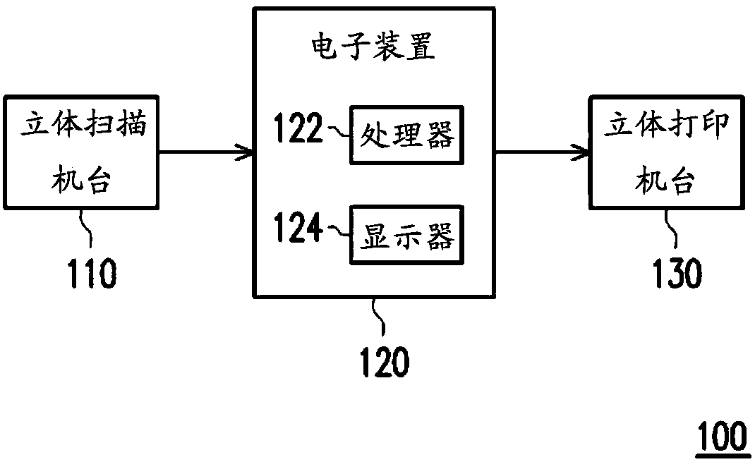
[0055] figure 1 It is a block diagram of an electronic system 100 for designing aids according to an embodiment of the present invention. Such as figure 1 As shown, the electronic system 100 mainly includes a three-dimensional scanning machine 110 and an electronic device 120 . The electronic device 120 mainly includes a processor 122 and a display 124 . The 3D scanning machine 110 is used to scan the body parts of the user to generate point cloud data of the body parts. For example, the user can place the position of the hand or the foot into the scanning area of ​​the 3D scanning machine 110 , so that the 3D scanning machine 110 can obtain point cloud data through the 3D scanning technology.

[0056] The processor 122 is, for example, a central processing unit (central processing unit; CPU), a programmable microprocessor (microprocessor), an embedded control chip, a digital signal processor (digital signal processor, DSP), an application specific integrated circuit (appli...


PUM


Abstract

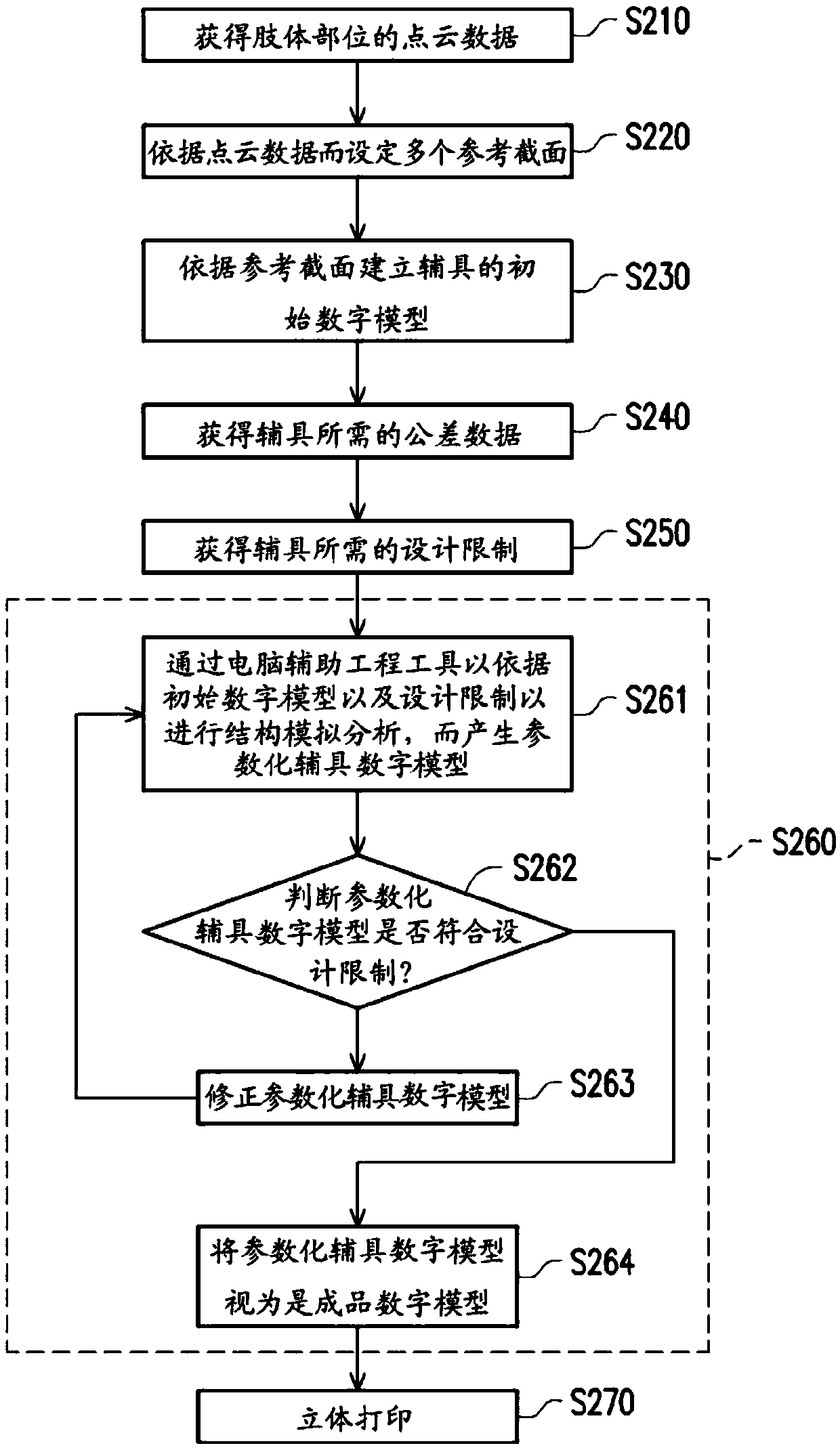
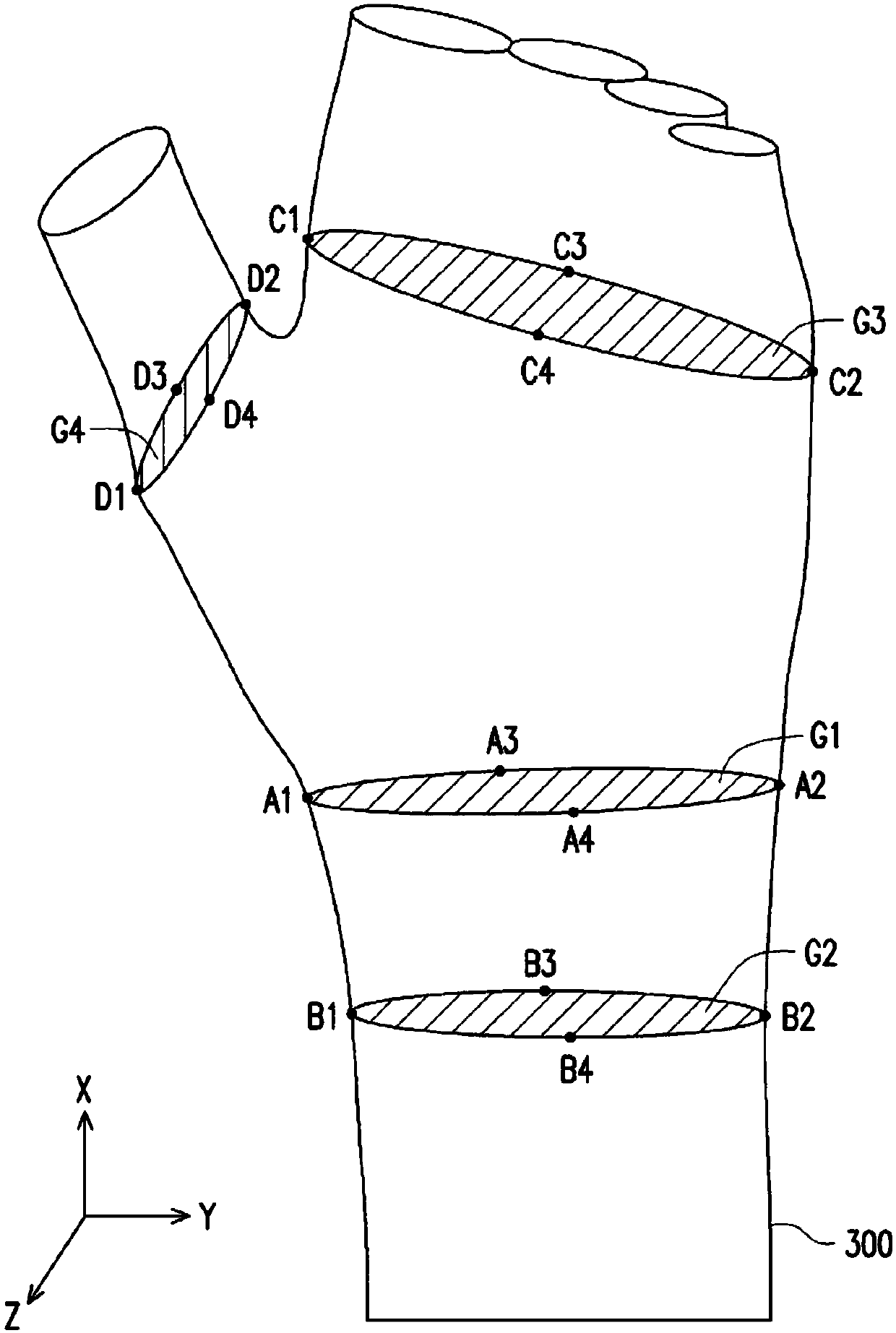
A design method of an assistive device and an electronic system of assistive device design are provided. The design method of the assistive device is adapted for electronic devices including a processor. The design method includes: obtaining a point cloud data of a limb part; determining a plurality of reference cross sections according to the point cloud data, wherein each of the reference crosssections is determined corresponding to bone protrusion feature points of the point cloud data, wherein the bone protrusion feature points are corresponding to the bony prominences of the limb parts respectively; establishing an initial digital model of the assistive device according to the reference cross sections; and performing a structural simulation analysis according to the initial digital model and design limitations to obtain a product digital model of the assistive device.

Description

technical field [0001] The invention relates to a product design and production technology, and in particular to a design method of an auxiliary device and an electronic system for designing the auxiliary device. Background technique [0002] When the limbs are injured, the movement will be affected. At this time, some equipment (such as plaster, crutches, protective gear, artificial limbs, etc.) is usually used for assistance. Such equipment is called assistive device. In terms of functionality, assistive devices may include mobility aids (e.g., wheelchairs, orthotic shoes, walking aids, crutches), assistive devices that assist limb functions (e.g., hand or leg prostheses, pencil holders, special spoons) ), life aids (safety alarm bells, ladder climbers), therapeutic or immobilizing aids (gypsum, back frame, waist support, knee pads, neck ring, pillow)...etc. The protective gear that is more common and often used by consumers is usually assistive gear related to physical a...

Claims


Application Information

Patent Timeline
Patent Type & Authority Applications(China)
IPC IPC(8): G06F17/50
CPCG06F30/00B33Y50/00G06T2219/012G06T2219/2021G06T19/20G06F30/23G06F30/20B29C64/386G06T2207/10028G06T17/00B33Y10/00B33Y50/02
Inventor 李暐赵玉麟沈志明戴明吉洪妙蓁
Owner IND TECH RES INST
Learn More