
Plant protection unmanned aerial vehicle

A technology for planting and protecting drones and racks, applied in aircraft parts, launchers, transportation and packaging, etc., can solve problems such as unfavorable long-term battery life, increase operation gap time, affect flight battery life and other problems, and achieve long-term battery life. Use, reduce the time between operations, and solve the effect of poor efficacy

Active Publication Date: 2015-06-03
广州快飞计算机科技有限公司
View PDF4 Cites 45 Cited by
  • Summary
  • Abstract
  • Description
  • Claims
  • Application Information

AI Technical Summary

Problems solved by technology

[0004] (1) The pump pressure system has a complex structure and a large volume, and the water pump with an outlet pressure between 0Mpa and 8Mpa is not only large in size, but also relatively heavy, which increases the load on the drone, affects the flight duration, and is inconvenient to carry; and If the water pump is small in size and light in weight, it cannot reach the required pressure;
[0005] (2) The nozzles are all fixed on the fuselage of the drone by screws or straps or on a long pole of a fuselage, which is inconvenient to disassemble and maintain;
[0006] (3) The upper part of the frame structure is used to install the power device, and the lower part includes a tripod and a frame for placing devices such as spraying objects, batteries and water pumps. In the prior art, the frame structure of the plant protection drone is generally integrated Structure, when the battery or the spray is exhausted, it is necessary to land the plant protection drone, and then replace the battery or replenish the spray separately, which increases the time between operations and reduces work efficiency; moreover, the integrated rack structure volume Larger, not conducive to long-term battery life, and transportation is more inconvenient

Method used


Image

  • Plant protection unmanned aerial vehicle
  • Plant protection unmanned aerial vehicle
  • Plant protection unmanned aerial vehicle

Examples


Embodiment approach

[0050] like Figures 8 to 10 As shown, the quick-release spray head 500 of this example includes a nozzle 51, a spray seat 52 for communicating with the pipe 200, a jacket assembly 53 for clamping the machine arm 12, a movable shaft 54, a spring 55 and a first support Part 56, the nozzle 51 is detachably fixed to the nozzle seat 52 and communicates with the pipeline 200 through the nozzle seat 52. A plug plate 521 extends from one side of the nozzle seat 52, and the plug plate 521 is opened for the movable shaft 54 ​​to insert. The insertion hole 5211 is movably connected to the jacket assembly 53, the first support member 56 is fixed to the jacket assembly 53, the movable shaft 54 ​​is movably connected to the first support member 56 and is perpendicular to the insertion plate 521, and the spring 55 is sleeved on the movable shaft 54 ​​, one end of the spring 55 is in contact with the first support member 56 , and the other end of the spring 55 is connected with the lower end...


PUM


Abstract

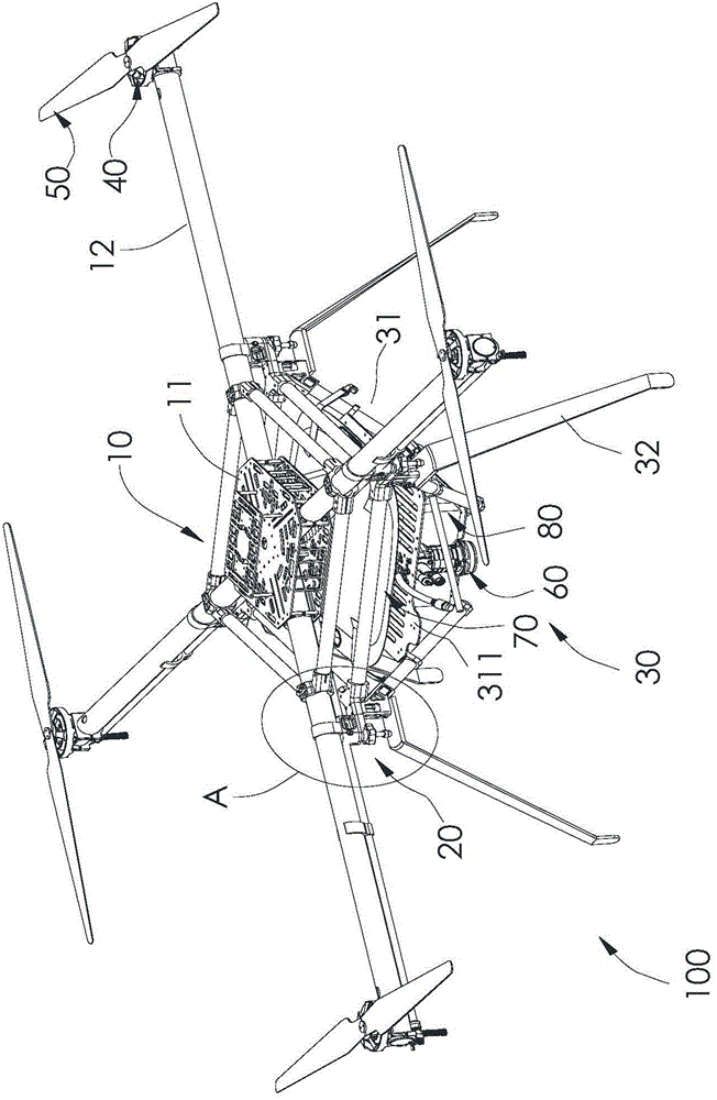
The invention discloses a plant protection unmanned aerial vehicle, which comprises a body, wherein the body comprises a power frame, a lower frame, quick release spray heads, pipelines and a water pump; the water pump is mounted at the lower frame; the lower frame is connected to the bottom of the power frame; the power frame comprises a first mounting rack and a plurality of arms arranged in the circumferential direction of the first mounting rack; one end of each arm is fixedly arranged on the first mounting rack; the other end of each arm is equipped with a first motor and rotor wings driven by the first motor to rotate; the quick release spray heads are fixedly arranged on the arms in a detachable manner and located below the rotor wings in a one-to-one correspondence manner; the water pump is communicated with the quick release spray heads by a multi-way joint and through the pipelines. The plant protection unmanned aerial vehicle is small in volume, high in work efficiency and long in endurance.

Description

technical field [0001] The present invention relates to a plant protection unmanned aerial vehicle. Background technique [0002] Plant protection drone is an unmanned aircraft used for agricultural and forestry plant protection operations. This type of unmanned aircraft consists of a flight platform (fixed-wing, single-rotor, multi-rotor), GPS flight control, and spraying mechanism. Or GPS flight control to achieve spraying operations, which can spray chemicals, seeds, powders, etc., and the spraying process is sprayed through the nozzle. [0003] However, the current crop protection drones have the following defects: [0004] (1) The structure of the pump pressure system is complex, the volume is huge, and the pump with the outlet pressure between 0Mpa-8Mpa is not only large in size, but also relatively cumbersome, which increases the load of the drone, affects the flight endurance, and is inconvenient to carry; If the pump is small in size and light in weight, it cannot...

Claims


Application Information

Patent Timeline
Patent Type & Authority Applications(China)
IPC IPC(8): B64D1/18
Inventor 张帆何建兵彭斌
Owner 广州快飞计算机科技有限公司
Learn More