
Extruder for fused filament fabrication 3D printer

a technology of extruder and fused filament, which is applied in the direction of additive manufacturing, manufacturing tools, additive manufacturing, etc., can solve the problems of large screw mechanism size, difficult installation into the 3d printer, and weight which limits the acceleration in the x-y plane and therefore the overall printing speed, so as to achieve the effect of high extrusion speed, high overall building speed of the 3d printer, and high filament material feed ra

Inactive Publication Date: 2017-06-08
RHOMBUS INT TECH
View PDF2 Cites 45 Cited by
  • Summary
  • Abstract
  • Description
  • Claims
  • Application Information

AI Technical Summary

Benefits of technology

The patent is about an improved extruder head for a 3D printer that allows for faster and more efficient printing. It is designed to prevent filament slippage and allows for the use of a thinner extruded material, which leads to faster overall printing speed. The improved design increases the area of friction between the filament and the pinch wheel, which results in higher feed rates for the filament material. This means the amount of material printed is exactly what is desired, even with high filament feeding rates. The design also prevents excessive wear and tear on the filament and printing mechanism, which can improve the lifespan of the printer.

Problems solved by technology

Although this type is typically capable of achieving high extrusion pressure, an important drawback is its weight which limits acceleration in the x-y plane and therefore overall printing speed.
Another drawback is the large size of the screw mechanism, which makes it difficult to install into the 3D printer.
Both increased resolution and increased extrusion speed result in higher nozzle pressure relative to the grippable surface area of the filament and therefore the available friction between the filament and the feeding device.
The gap between theoretical and actual extrusion speed increases due to slippage in the feeding device.
Current technology of 3D printers is limited to extrusion of around 10 mm3 / s which is equivalent to 80 mm / sec extrusion speed with a 0.4 mm diameter nozzle, using ABS material.
Over this limit slippage becomes unacceptable, which can lead to poor quality and build interruptions.

Method used


Image

  • Extruder for fused filament fabrication 3D printer
  • Extruder for fused filament fabrication 3D printer
  • Extruder for fused filament fabrication 3D printer

Examples


Embodiment Construction

[0013]

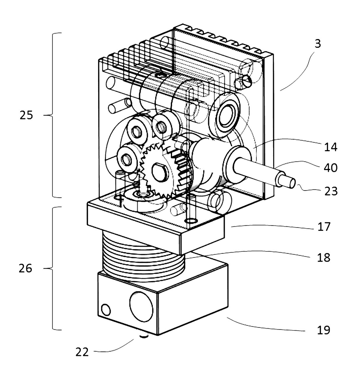
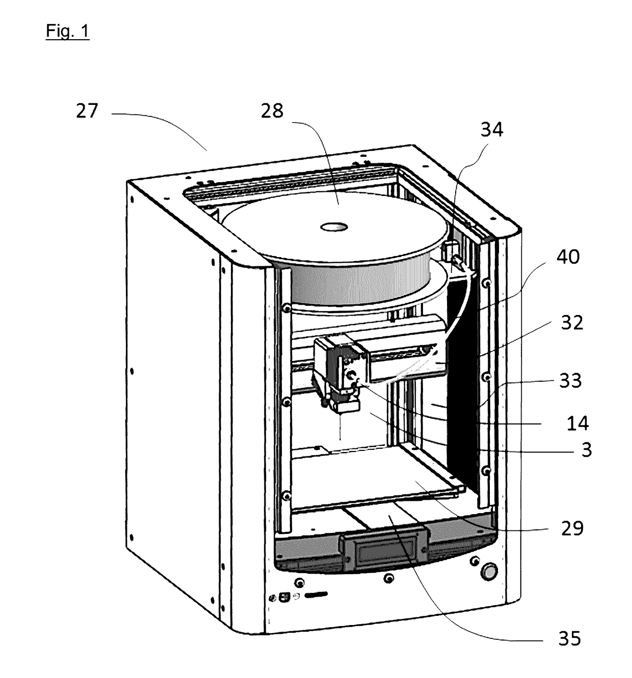
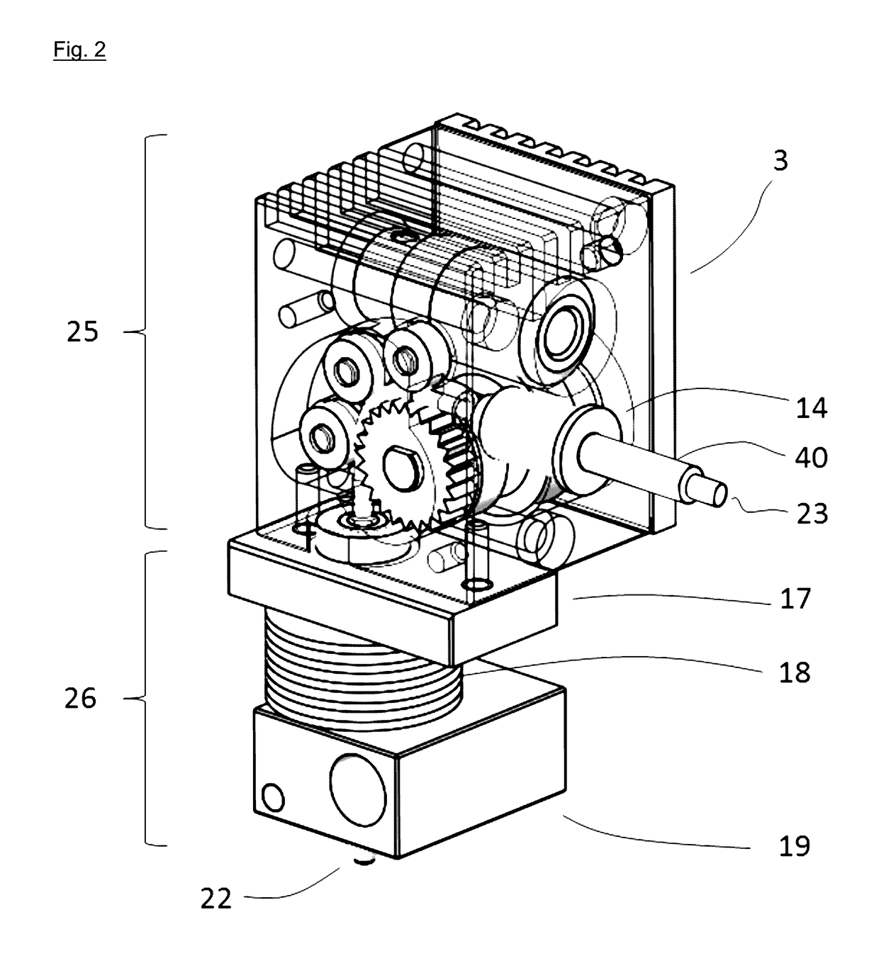
Table of Components 1 Stepping motor 2 Motor mount 3 Extruder head 4 Worm gear 5 Extruder bracket 6 Cooling fan 7 Cold end heat sink 8 8a Cover A, 8b Cover B 9 9a-9f Support rollers10 Pinch wheel11 Pinch wheel shaft12 Worm wheel13 Worm wheel bearing14 Filament inlet15 Pinch wheel bearing16 Hot end pipe17 Thermal insulator18 Hot end heat sink19 Heater block20 Temperature sensor21 Heater22 Nozzle23 Filament24 Filament outlet direction25 Cold end26 Hot end27 3D printer28 Filament roll29 Building surface30 Filament contact angle v31 Support roller center distance d32 Horizontal beam33 Vertical beam34 Filament roll support beam35 Building surface linear guide36 Partly molten polymer37 Molten polymer38 Extruded string of molten polymer39 Filament guide groove40 Filament guide tube41 Filament inlet direction

[0014]Referring to FIG. 1, according to the preferred embodiment, there is provided a 3D printer 27 having a horizontal build surface 29 movable in the horizontal Y direction guid...


PUM

PropertyMeasurementUnit
contact angleaaaaaaaaaa
thickaaaaaaaaaa

Abstract

Disclosed is an improved extruder head for a fused filament fabrication 3D printer. It would be beneficial with a thinner nozzle diameter and higher extrusion speed without slippage in the feeding mechanism. The proposed improved extruder head enables extrusion of thinner extruded material at a higher extrusion speed without any slippage in filament feeding mechanism, thereby allowing higher overall building speed of the 3D printer with high quality build. Higher feed-rate of the filament material is achieved by increased usable friction between pinch wheel and filament by increasing the grippable area of the filament. This is done by feeding the filament into the feeding mechanism at an angle different to the outlet angle and routing it around the pinch wheel, back supported by a plurality of support rollers, so that the filament is in frictional contact with the pinch wheel along a greater part of its circumference, thereby increasing the surface contact area between the pinch wheel and the filament. Owing to non-slippage of the filament feeder, nominal volume of extruded material is exactly the same as desired volume with high filament feeding rate. Due to compact feeding mechanism, total mass of extruder kept small enough to enable higher acceleration of the printing nozzle resulting higher printing speed. Owing to horizontal loading of the filament material, feed roll can be mounted just above the extruder for smooth filament supply and compact size of 3D printer.

Description

CROSS-REFERENCE TO RELATED APPLICATIONS[0001]This application is a continuation of, and claims the benefit of PCT application PCT / IB2014 / 062163 filed Jun. 12, 2014, the contents of which are incorporated herein in their entirety.TECHNICAL FIELD[0002]This invention relates to additive manufacturing systems, more particularly the extrusion head mechanism, or extruder, of a fused filament fabrication system.BACKGROUND ART[0003]Fused Filament Fabrication is one of several known methods of 3D printing, where physical components can be manufactured directly from a 3D CAD (Computer Aided Design) model using an additive approach where material is deposited on a horizontal building surface layer by layer. Such layers are typically between 0.05 to 1.0 mm thick depending on the technology used and interpreted by translating ‘slices’ of the 3D CAD model into movement of an extrusion head for depositing material. In fused filament fabrication, the deposition technology is extrusion of polymer vi...

Claims


Application Information

Patent Timeline
Patent Type & Authority Applications(United States)
IPC IPC(8): B29C47/00B29C31/04B29C67/00B29C47/10B29C47/08B29C48/05B29C48/02
CPCB29C47/0014B29C47/1045B29C31/042B29C67/0051B29C47/0866B29C48/02B29C48/2888B29C48/05B29C48/266B29C48/2886B29C64/118B29C64/321B29C64/106
Inventor HISHIKI, TERUO
Owner RHOMBUS INT TECH
Learn More