Acousto-optic deflector device for improving laser scanning angle
An acousto-optic deflector, laser scanning technology, applied in instruments, optics, nonlinear optics, etc., can solve the problems of difficult to meet the scanning requirements of large angles, small scanning angles, etc., to achieve low power consumption, low operating voltage, scanning fast frequency effect
- Summary
- Abstract
- Description
- Claims
- Application Information
AI Technical Summary
Problems solved by technology
Method used
Image

Examples
Embodiment 1
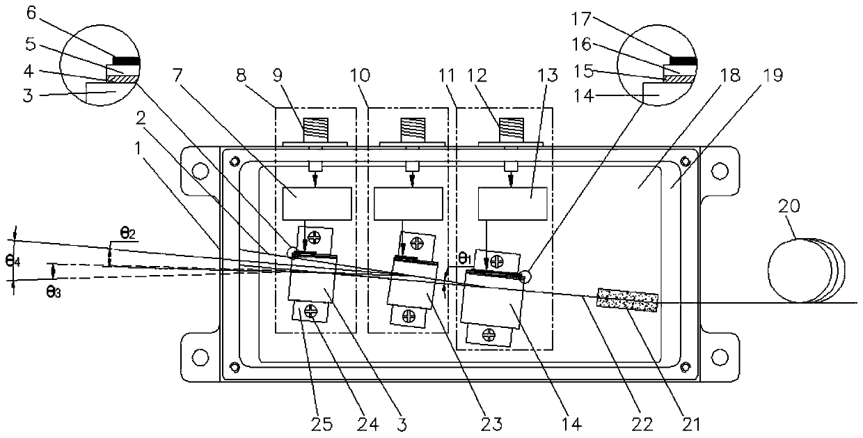
[0032] Such as figure 1 As shown, a two-stage acousto-optic deflector assembly of the present invention includes a housing 1, a mounting plate 18 and a buffer layer 19 are installed in the housing 1, and an acousto-optic deflector 8, an acousto-optic deflector 8, and an acousto-optic deflector A deflector 10 , an acousto-optic modulator 11 and a fiber collimator 21 .
[0033] Among them, the acousto-optic deflector 8 is mainly composed of the acousto-optic medium 3, the bonding layer 4, the transducer 5, the surface electrode 6, the matching network 7, the high-frequency socket 9, the screw 24 and the fixing plate 25; A fixed plate 25 is connected below the optical medium 3, and the acousto-optic medium 3 is fixed on the mounting plate by screws 24 on the fixed plate 25; a bonding layer 4 is connected above the acousto-optic medium 3; A transducer 5 is installed above the 4; the acousto-optic medium 3 is connected to the meter electrode 6 through the transducer 5, and a match...
Embodiment 2
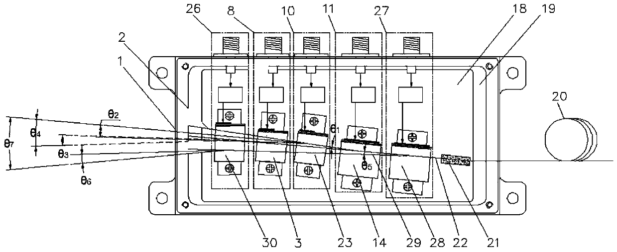
[0046] Such as figure 2 As shown, the present embodiment provides a three-stage AOD assembly, including a housing 1, a mounting plate 18 and a buffer heat dissipation layer 19 are installed in the housing 1, and an AOD 8, an acoustic Optical deflector 10 , acousto-optic deflector 26 , acousto-optic modulator 11 , acousto-optic modulator 27 and fiber collimator 21 . Compared with the 2-stage AOD assembly, the 3-stage AOD assembly adds an AOD 26 and an AOM 27 .
[0047] The AOD 8, the AOD 10 and the AOD 26 are all designed according to the theory of anomalous AOD, so the diffracted light can obtain a larger scanning angle. Through precise design and processing, the scanning angles of the three AODs can all be θ 0 .
[0048] The working principle of the AOD 8, the AOD 10 and the AOM 11 is the same as that of the 2-stage AOD assembly.
[0049] The working principle of the acousto-optic modulator 27 is: the radio frequency signal is input from the high-frequency socket, and th...
Embodiment 3
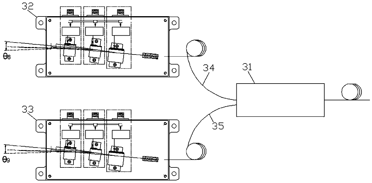
[0055] Such as image 3 As shown, this embodiment provides a two-way two-stage fiber optic AOD assembly, including a split fiber switch 31 , a two-stage AOD assembly 32 and a two-stage AOD assembly 33 . The optical fiber switch 31 divides the light into two paths: light splitting 34 and light splitting 35 . The split light 34 is deflected and scanned by the two-stage acousto-optic deflector assembly 32, and the scanning angle is θ 8 , θ 8 = 2θ 0 . The split light 35 is deflected and scanned by the two-stage acousto-optic deflector assembly 33, and the scanning angle is θ 9 , θ 9 = 2θ 0 . The total scan angle of this 2-stage fiber AOD assembly is θ 9 +θ 8 = 2θ 0 +2θ 0 =4θ 0 , Compared with the ordinary single acousto-optic deflector, the scanning angle is increased by 3 times.
[0056] Among them, as a realizable way, if the optical fiber switch 31 is divided into n channels, then it needs to be connected with n 2-stage acousto-optic deflector components. At this t...
PUM
 Abstract
Description
Claims
Application Information
 - R&D
- Intellectual Property
- Life Sciences
- Materials
- Tech Scout
- Unparalleled Data Quality
- Higher Quality Content
- 60% Fewer Hallucinations
Browse by: Latest US Patents, China's latest patents, Technical Efficacy Thesaurus, Application Domain, Technology Topic, Popular Technical Reports.
© 2025 PatSnap. All rights reserved.Legal|Privacy policy|Modern Slavery Act Transparency Statement|Sitemap|About US| Contact US: help@patsnap.com