
Normal-position turning device for railway vehicle testable track wheel

A technology for railway vehicles and rail wheels, which is applied to turning equipment, turning equipment, metal processing equipment, etc., can solve the problems of large tool holder size, complicated installation and use, and difficulty in popularization and use, and achieve simple turning repair and light weight , The effect of high power output efficiency

Pending Publication Date: 2019-08-16
SOUTHWEST JIAOTONG UNIV
View PDF0 Cites 0 Cited by
  • Summary
  • Abstract
  • Description
  • Claims
  • Application Information

AI Technical Summary

Problems solved by technology

[0004] At present, the main repair method of the track wheel is: disassemble the track wheel and transport it to a processing workshop equipped with a large CNC lathe, install the track wheel on the lathe, use the top positioning for turning, and then pack and ship back to the original test bench for assembly , the entire overhaul process takes several weeks, which is inefficient and expensive
In recent years, there is also a method of using a servo motor to drive a CNC tool holder to repair the track wheel; but it adopts a traditional tool holder structure, the size of the tool holder is too large, and the installation and use are too complicated, so it is difficult to popularize and use

Method used


Image

  • Normal-position turning device for railway vehicle testable track wheel
  • Normal-position turning device for railway vehicle testable track wheel
  • Normal-position turning device for railway vehicle testable track wheel

Examples


Embodiment

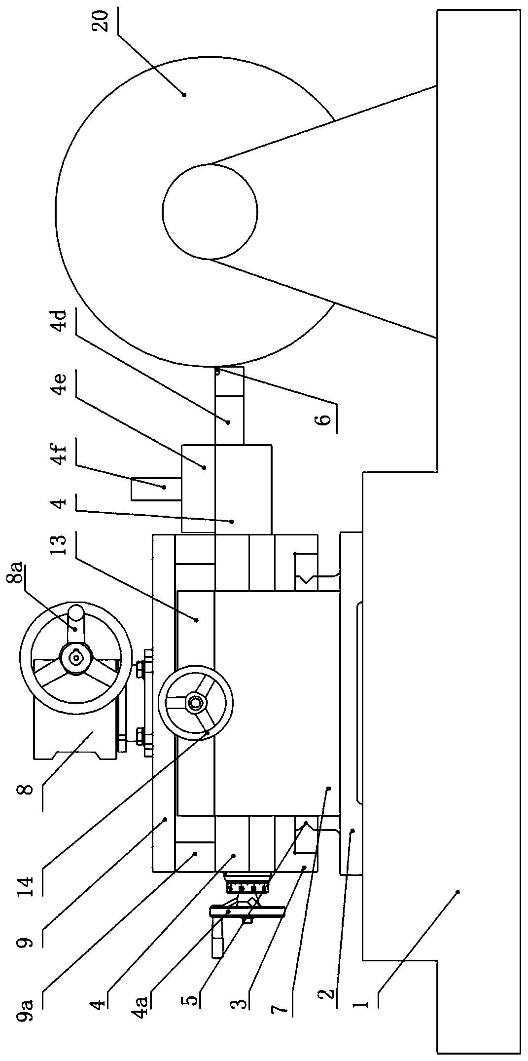
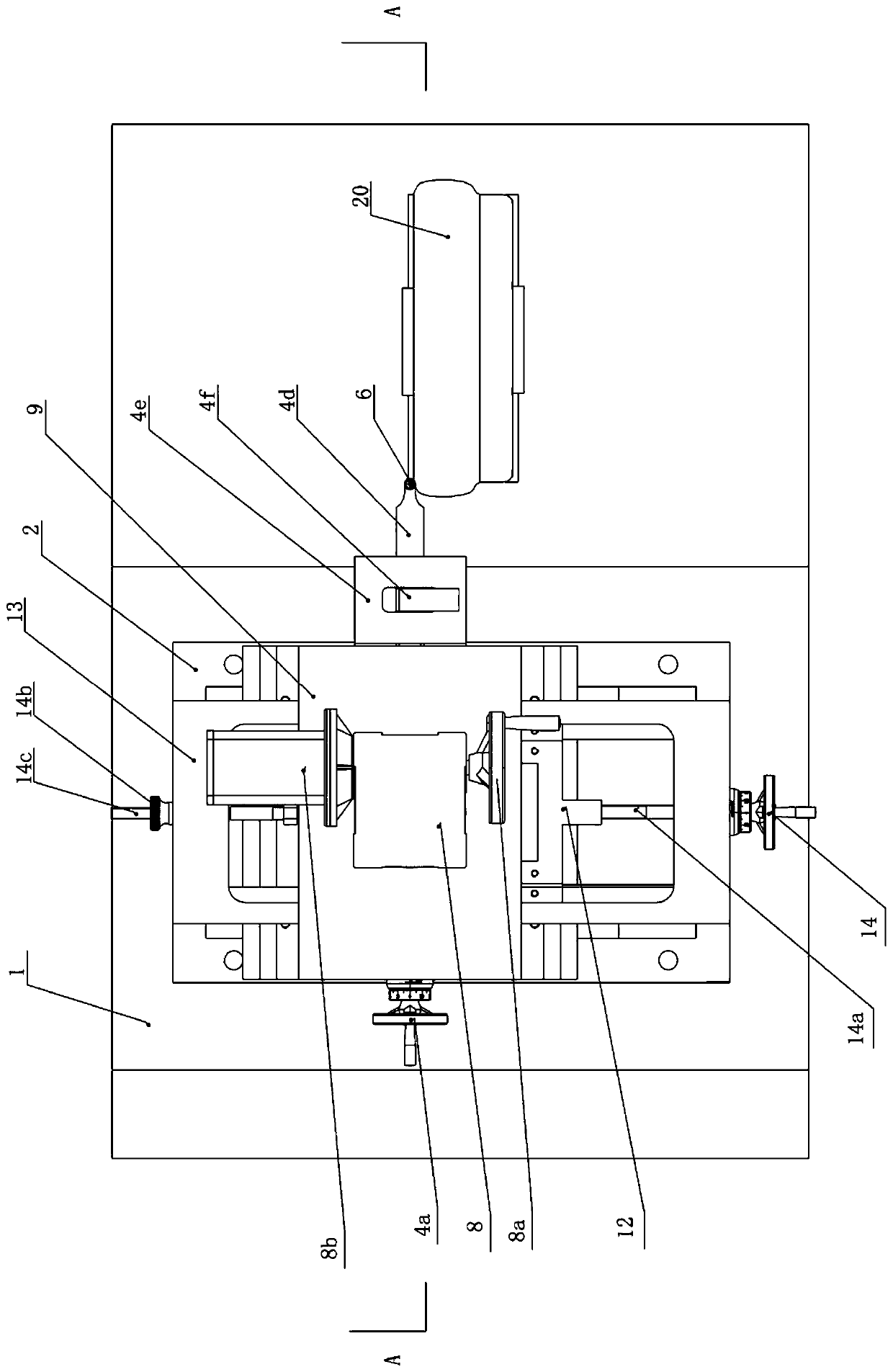
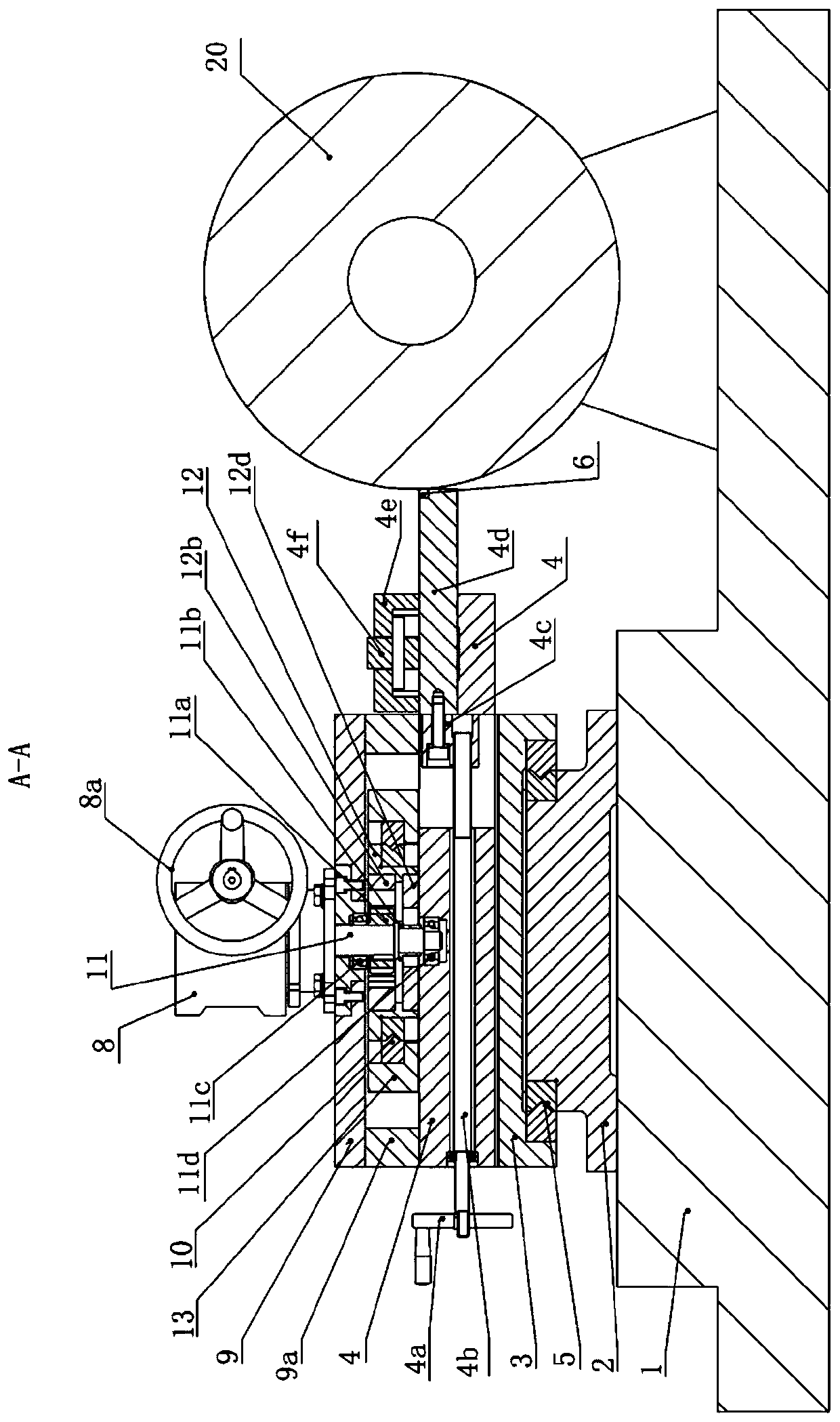
[0040] Figure 1-3 Shown, a kind of specific embodiment of the present invention is, a kind of in-situ turning device of rail wheel of railway vehicle test bench, comprises: the rail wheel base 1 of rail vehicle rolling test bench, the right part of rail wheel base 1 installation Rail wheel 20 is characterized in that:

[0041]The upper left part of the track wheel base 1 is equipped with a two-dimensional mobile platform, the upper part of the two-dimensional mobile platform is a horizontal mobile platform 4, the middle part is a vertical mobile platform 3, and the bottom part is a base plate 2;

[0042] In the transverse through hole of described transverse mobile platform 4, be provided with feed screw mandrel 4b, cutter bar connecting block 4c and turning tool bar 4d successively from left to right; The knife hand wheel 4a is connected, the screw thread at the right end of the feed screw 4b matches the threaded hole of the knife bar connecting block 4c, the right end of t...


PUM


Abstract

The invention provides a normal-position turning device for a railway vehicle testable track wheel. According to the main constitution, a two-dimensional moving platform is installed on the left upperportion of a base of the track wheel, a transverse moving platform is arranged on the upper portion of the two-dimensional moving platform, the transverse moving platform is provided with a cutter feeding mechanism, a round turning cutter is arranged at the right end of the cutter feeding mechanism, an upper beam frame is arranged above the transverse moving platform, a guide frame is longitudinally connected into a rectangular inner cavity of the upper beam frame in a sliding manner, an arc-shaped rack plate is fixedly embedded into the upper portion of an inner cavity of the guide frame, aguide through groove plate is fixed to the lower portion of the inner cavity of the guide frame, a transverse top plate is arranged above the upper beam frame, a profiled shaft of a corner type speedreducer on the transverse top plate sequentially penetrates through the transverse top plate, the inner cavity of the arc-shaped rack plate and a guide groove of the guide through groove plate downwards and is inserted into a drive hole of the transverse moving platform, a gear on the profiled shaft is matched with the tooth edge of the inner cavity of the arc-shaped rack plate, and the center line of the guide through groove is the sum of the appearance curve of the cross section of the standard track wheel and the equidistant line of the outer side of the radius of the round turning cutter.The normal-position turning device is simple in structure, short in maintenance time and low in expense, and maintenance operation is convenient.

Description

technical field [0001] The invention relates to an in-situ turning device for rail wheels of a railway vehicle test bench. [0002] technical background [0003] Rolling test rigs are frequently used in the railway industry for simulated running tests of rolling stock or its bogies. The rolling test bench is a large-scale fixed test equipment specially used for the running part of railway vehicles. It uses the track wheel with the same tread profile as the rail tread to roll against the wheel and support the wheel to realize the simulation of the rail track. The diameter of the track wheel of the test bench is usually only 1.0-1.8 meters, and the circumference is 3-6 meters, which is not much different from the wheel. Therefore, the wear rate of the track wheel is not much different from that of the wheel, and the wear rate is accelerated when the traction or braking test is carried out. Because this kind of wear is random, it presents inhomogeneity along the circumference...

Claims


Application Information

Patent Timeline
IPC IPC(8): B23B5/04B23B1/00
CPCB23B5/04B23B1/00
Inventor 周文祥文永翔李永康向星峄张进张晓阳陈阳祝向阳孔振文
Owner SOUTHWEST JIAOTONG UNIV
Learn More