
Fixing unit

A technology for fixing units and fixing components, which is applied in the fields of medical science, dentistry, dental prosthetics, etc., and can solve problems such as patient interference

Inactive Publication Date: 2018-09-18
ELSNER GLOBAL LLC
View PDF10 Cites 2 Cited by
  • Summary
  • Abstract
  • Description
  • Claims
  • Application Information

AI Technical Summary

Problems solved by technology

The unrelenting force applied to the tooth and transmitted to the groove bone can cause disturbing effects on the patient

Method used


Image

  • Fixing unit
  • Fixing unit
  • Fixing unit

Examples


Embodiment Construction

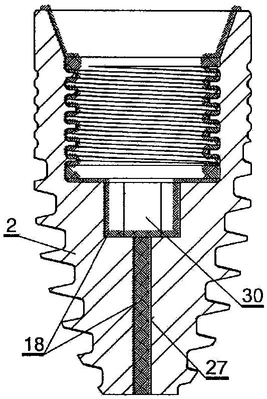
[0099] The invention relates to several types of fixation units 3, each of which can be elastically mounted in any implant 2 according to the invention. To this end, medical silicone 18 is placed between the implant 2 and the fixation element 5 of the dental appliance 31 . In this way, the dental appliance 31 built into the implant becomes slightly elastic and has cushioning characteristics in the periodontal tissue 1 . In addition, this solution ensures a seal between the fixation element 5 of the fixation unit 3 and the implant 2 , preventing the occurrence of so-called bacterial pumps caused by microscopic movements, and bacteria cannot enter the interior of the implant 2 .

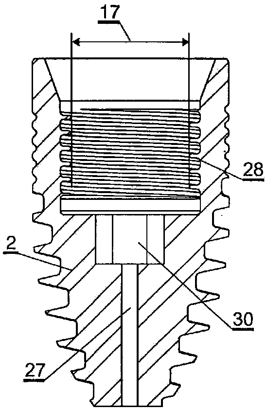
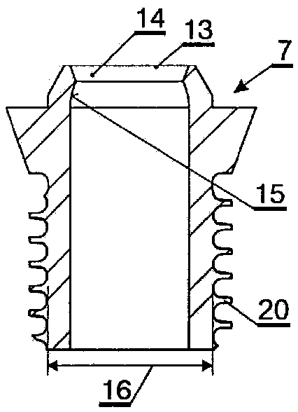
[0100] In order to fasten the fixation unit 3 in the implant 2 by means of elastic biocompatible silicone 18, the Figure 5 scheme. figure 1 shows the design of the implant, figure 2 The position of the silicone gel 18 without the intermediate part 7 is shown with the intermediate part 7 in the im...


PUM


Abstract

The invention relates to a fixing device which can secure a dental device into a dental implant, the fixing device comprising: a threaded shank (4); and a fixing element (5) for securing the threadedshank (4) to the implant. The fixing element (5) consists of an insertion piece (6) and an intermediate piece (7). Then end (9) of the insertion piece (6) is hemispherical. The inner end of the threaded shank 4 is a sphere shell (12) the inner spherical surface (11) of which is widened towards the insertion piece (6). The cross-section of an outer spherical surface (10) of the sphere shell (12) perpendicular to the axis of rotation (32) of the threaded shank (4) is a regular polygon. The inner surface (15) of the intermediate piece (7) is a sphere-like shell. The number of the angles of the polygon of the inner surface (15) of the intermediate piece (7) equals to the number of the angles of the regular polygon formed at the inner end (8) of the threaded shank (4).

Description

[0001] This application is a divisional application of the patent application with the filing date of January 3, 2014, the application number of 201480009508.6, and the title of "Dental Appliance Fixing Unit". technical field [0002] The invention relates to a dental appliance fixing unit which can advantageously be fastened elastically to a dental implant and whose angular position can be adjusted arbitrarily. The fixation unit comprises: a threaded shank protruding from the implant, tiltable in all directions; and a fixation element for fastening the threaded shank to the implant. The fixation element consists of an insert and an intermediate piece provided with a drill hole through which a threaded shank passes in order to fasten the insert to the implant. The end of the insert and the inner end of the threaded shank are pivotally attached to each other. The inner end of the threaded shank is positioned between the end of the insert and the upper end of the intermediate p...

Claims


Application Information

Patent Timeline
Patent Type & Authority Applications(China)
IPC IPC(8): A61C8/00
CPCA61C8/0053A61C8/0057A61C8/006A61C8/0063A61C8/0074A61C8/0086A61C8/0054A61C8/0089
Inventor 埃德温·埃尔斯纳
Owner ELSNER GLOBAL LLC
Learn More