


Quick Research
Generate reliable direction feasibility study reports for your R&D in just a few steps.

Technical Q&A
Discover and master advanced knowledge NOW. Basics, ideas, possibilities, all at once.

Find Solutions
As an expert in R&D theories, this can generate solutions to your technical problems instantly.

Evaluate Feasibility
Analyze your overall solution with one click, know your potential R&D risks in advance.

Monitor Landscape
Get weekly tech updates, stay abreast of the latest tech innovations and key insights.
Scattered light and fluorescent light bimodal flow imaging system
A technology of scattering fluorescence and imaging system, which is applied in the field of optical instruments, can solve problems such as identification difficulties, cell size counting errors, insufficient spectral imaging channels, etc., and achieve the effect of expanding the scope of application and compact structure
- Summary
- Abstract
- Description
- Claims
- Application Information
AI Technical Summary
Problems solved by technology
Method used
Image


Examples
example 1
[0047] Example 1: Detection of marine phytoplankton cells
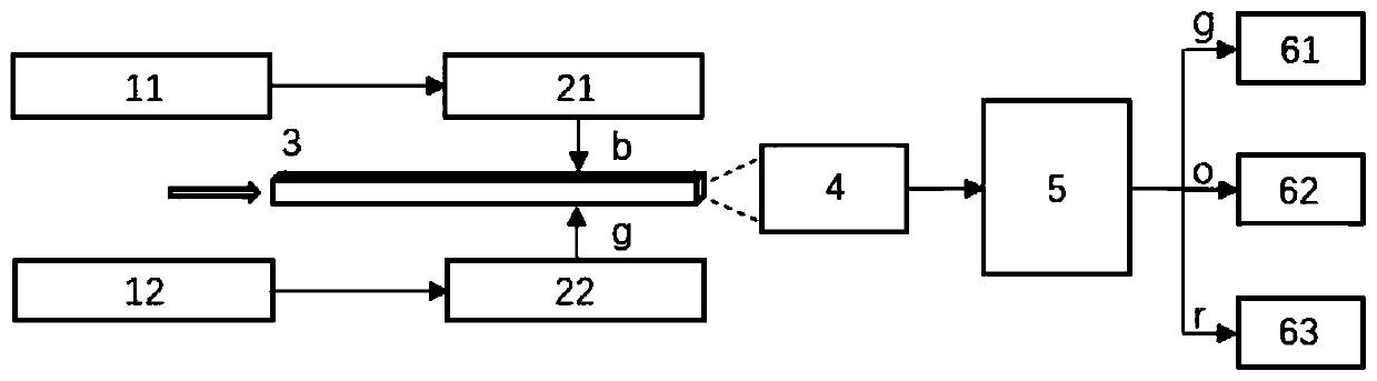
[0048] As attached to the manual figure 2 As shown, the multicolor orthogonal lighting unit A specifically includes two sets of lasers 11, 12 and beam shaping modules 21, 22 that cooperate with each other. The center wavelengths of the laser 11 and the laser 12 are 445nm (blue light b) and 532nm (green light g) respectively. ), corresponding to the excitation peaks of chlorophyll a and phycoerythrin in marine phytoplankton cells, respectively. Taking the excitation light path of blue light b as an example, after passing through the beam shaping module 21, the Gaussian beam emitted by the laser 11 is shaped and the illumination direction is adjusted to be perpendicular to the flow direction of the sample in the sample tube 3, and the illumination beam coincides with the focal plane of the imaging objective lens 4 , perpendicular to the flow side of the injection. The phytoplankton cell particles will scatter the ill...
example 2
[0049] Example 2: For the detection of freshwater phytoplankton cells
[0050] The main difference between freshwater phytoplankton and seawater phytoplankton is that the ratio of phycoerythrin and phycocyanin in the cells is different. Many marine phytoplankton cells contain phycoerythrin, while freshwater phytoplankton cells contain most phycocyanin. Therefore, Example 2 and The main difference of Example 1 lies in the excitation and collection of phycoerythrin / phycocyanin autofluorescence.
[0051] As attached to the manual image 3 As shown, the multi-color orthogonal lighting unit A specifically includes two sets of lasers 11, 13 and beam shaping modules 21, 23 that work together. The center wavelengths of the laser 11 and the laser 13 are 445nm (blue light b) and 633nm (red light r) respectively. ), corresponding to the excitation peaks of chlorophyll a and phycocyanin in freshwater phytoplankton cells, respectively. Taking the red excitation light path as an example, ...
example 3
[0052] Example 3: For the detection of various phytoplankton cells
[0053] If two sets of systems are needed to observe and analyze seawater phytoplankton and freshwater phytoplankton, it is obviously troublesome. Therefore, the excitation and collection methods of phycoerythrin and phycocyanin autofluorescence in the above-mentioned embodiments can be combined for a comprehensive analysis of seawater and freshwater phytoplankton in one system.
[0054] As attached to the manual Figure 4 As shown, the multi-color orthogonal lighting unit A specifically includes three sets of lasers 11, 12, 13 and beam shaping modules 21, 22, 23 used in conjunction with each other. In this embodiment, three lasers are used to cover more excitation peaks. The center wavelengths are 445nm (blue light b), 532nm (green light g) and 633nm (red light r) respectively. Taking the green light excitation optical path as an example, after passing through the beam shaping unit 22, the Gaussian beam emi...
PUM
| Property | Measurement | Unit |
|---|---|---|
| Horizontal resolution | aaaaa | aaaaa |
Abstract
Description
Claims
Application Information
 - R&D Engineer
- R&D Manager
- IP Professional
- Industry Leading Data Capabilities
- Powerful AI technology
- Patent DNA Extraction
Browse by: Latest US Patents, China's latest patents, Technical Efficacy Thesaurus, Application Domain, Technology Topic, Popular Technical Reports.
© 2024 PatSnap. All rights reserved.Legal|Privacy policy|Modern Slavery Act Transparency Statement|Sitemap|About US| Contact US: help@patsnap.com