Submerged floating tunnel pipe section attitude measuring device and submerged floating tunnel pipe section attitude test system and method
A floating tunnel and measuring device technology, which is applied to measuring devices, radio wave measuring systems, and optical devices, etc., can solve problems such as difficulty in ensuring accuracy, complicated derivation, complex DC components and interference noise, and meet the requirements of test accuracy. , Easy to install and use, improve the effect of measurement accuracy
- Summary
- Abstract
- Description
- Claims
- Application Information
AI Technical Summary
Problems solved by technology
Method used
Image
Examples
Embodiment 1
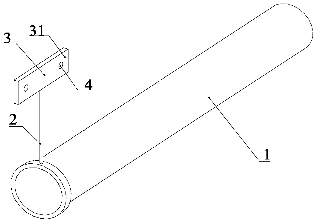
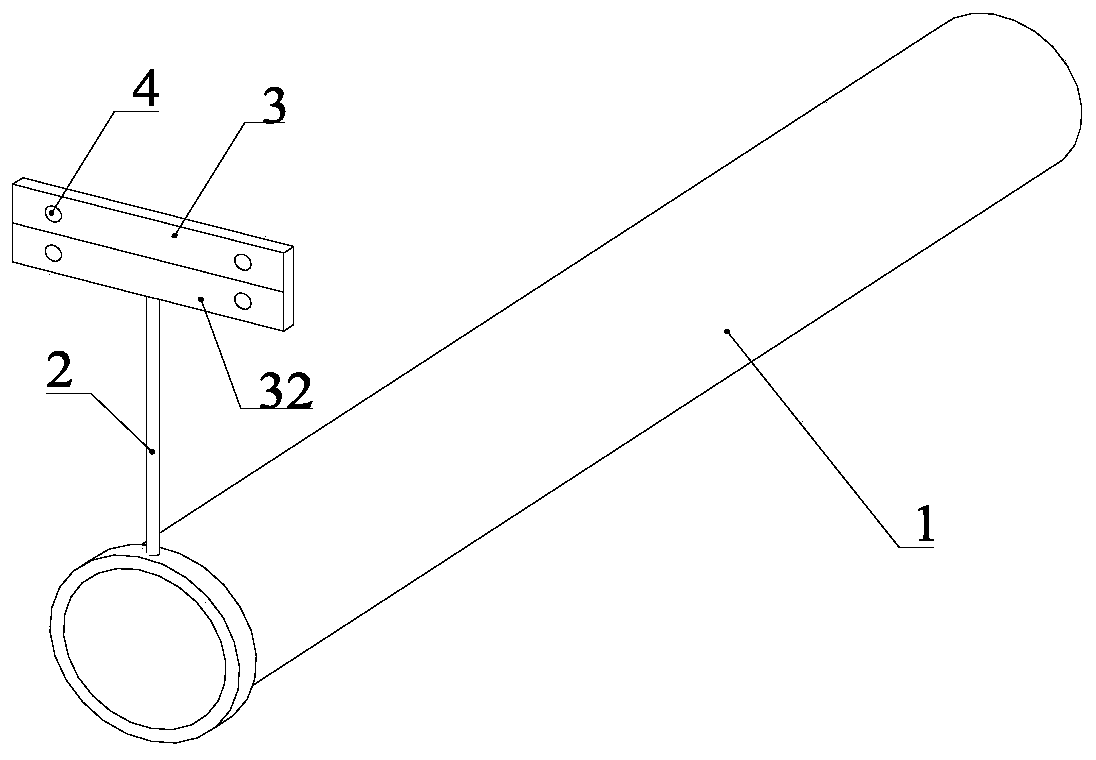
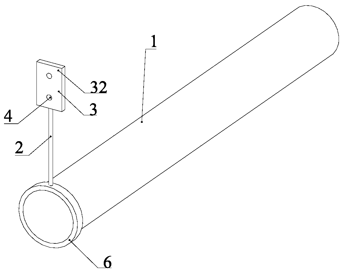
[0068] A floating tunnel pipe section attitude measurement device, including a support 2 for fixing on a floating tunnel model pipe section 1, a background plate 3 is welded and fixed on the support 2, and the background plate 3 is provided with several characteristic surfaces. A plurality of feature points 4 are set on the feature surface. Since the bracket 2 has a certain height, the feature point 4 on the background plate 3 can be completely exposed to the water surface, and the setting of the feature point 4 should satisfy whether the UX, UY, UZ, ROTX, The motion components in the six directions of ROTY and ROTZ.
[0069] Although the position and direction of the feature surface and the distribution form of the feature points do not affect the measured attitude of the model pipe section. However, for the convenience of calculation, the model pipe section 1 in this embodiment adopts a circular pipe structure, and the distribution of characteristic surfaces and characteris...
Embodiment 2
[0078] Such as Figure 13-Figure 14 As shown, in the overall physical model test of the floating tunnel, when the buoyancy of the model pipe section 1 is less than its own gravity, the anchoring system is designed as a buoy type, and the buoyancy-to-weight ratio of the model pipe section is generally designed to be slightly less than 1. When using the bracket conversion method to measure the device, it should be installed in the middle of the two buoys 9, and ensure that the clamp 6 and the model pipe section 1, the bracket 2 and the clamp 6, the background plate 3 and the bracket 2 are firmly connected, and no relative displacement occurs. When measuring the buoy-type floating tunnel, the elevation of the feature point 4 should be greater than the top elevation of the buoy 9, so as to avoid the influence of the buoy 9 on the measurement.
[0079] For buoy-type floating tunnels, the position of the clamp 6 is not at the buckle position of the model pipe section 1 itself, so th...
Embodiment 3
[0082] A method for testing the attitude of a pipe section of a floating tunnel, comprising the following steps:
[0083] Step 1: Make the bracket 2, the bracket 2 can be a rod-shaped structure, such as Figure 9 As shown, it can also be a truss structure, such as Figure 10 shown.
[0084] Step 2: Connect the clamp 6 to the model pipe section 1 on the shore, such as Figure 15-Figure 16 As shown, the clamp 6 includes two clamp assemblies 61. During installation, the two clamp assemblies 61 are respectively clamped with the model pipe section 1, and then the two clamp assemblies 61 are connected by welding, so that the clamp 6 is connected with the model pipe section 1.
[0085] Step 3: If Figure 17 As shown, the background plate 3 with feature points 4 is made according to the requirements, and the colors of the feature points 4 and the background plate 3 should have obvious grayscale contrast according to the shooting and capturing requirements of the high-speed camera ...
PUM
 Abstract
Description
Claims
Application Information
 - R&D
- Intellectual Property
- Life Sciences
- Materials
- Tech Scout
- Unparalleled Data Quality
- Higher Quality Content
- 60% Fewer Hallucinations
Browse by: Latest US Patents, China's latest patents, Technical Efficacy Thesaurus, Application Domain, Technology Topic, Popular Technical Reports.
© 2025 PatSnap. All rights reserved.Legal|Privacy policy|Modern Slavery Act Transparency Statement|Sitemap|About US| Contact US: help@patsnap.com


