
Three-mode digital holography microscopy imaging system

A digital holographic microscopy and imaging system technology, applied in instruments, measuring devices, optical devices, etc., can solve the problems of bulky instruments, low timeliness, and low resolution of lateral imaging, and achieve high system utilization and convenience. synthetic effect

Active Publication Date: 2019-08-09
NANJING UNIV OF SCI & TECH
View PDF6 Cites 1 Cited by
  • Summary
  • Abstract
  • Description
  • Claims
  • Application Information

AI Technical Summary

Problems solved by technology

The invention patent "Transmissive Digital Holographic Microscopic Imaging Device Based on Telecentric Optical Structure" (application number: 201510631831.3) has greatly improved the imaging quality of the system, but due to the illumination method of coherent light, the horizontal imaging effect of the system It is far inferior to the traditional microscope with incoherent light as the illumination method, so the general digital holographic microscope has low lateral imaging clarity and has been criticized by biomedical researchers
However, inverted fluorescence microscopes and digital holographic microscopes are not only expensive, but also quite bulky
At the same time, after obtaining the bright field and fluorescence information of the sample under the inverted fluorescence microscope, it is difficult to find a completely consistent sample area in the digital holography system, which brings difficulties to the synthesis of lateral intensity information and axial thickness information. And if the observations are made separately in the two systems, the timeliness of the work is very low

Method used


Image

  • Three-mode digital holography microscopy imaging system
  • Three-mode digital holography microscopy imaging system
  • Three-mode digital holography microscopy imaging system

Examples


Embodiment Construction

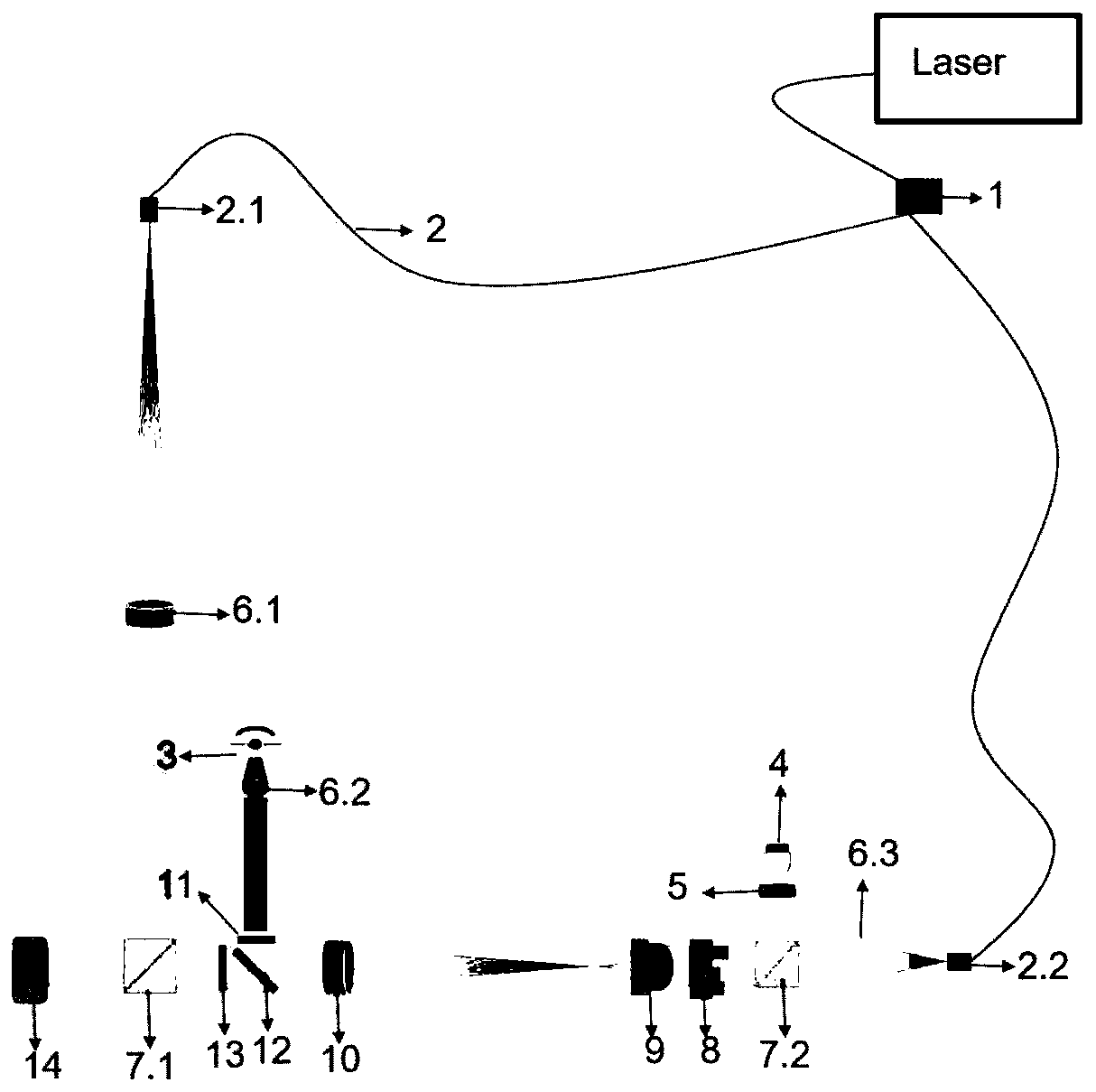
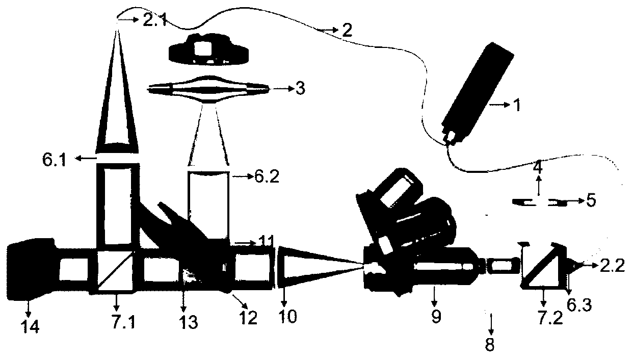
[0011] Combine figure 1 with figure 2 The three-mode digital holographic microscopy system of the present invention that takes into account both fluorescence and bright field includes He-Ne laser 1, fiber splitter 2, mercury lamp 3, white light LED 4, ground glass sheet 5, and first beam expanding collimator 6.1 , The second beam expander collimator 6.2, the third beam expander collimator 6.3, the first beam splitting prism 7.1, the second beam splitting prism 7.2, microscope objective 9 (different magnification can be switched), tube lens 10, excitation color filter 11 , Color filter wheel 12 (two-way color filter, 632nm band stop filter or / and 632nm band pass filter are set on the color filter wheel 12), absorption filter 13 and camera 14, the He-Ne laser 1, white light LED 4 and mercury lamp 3 It can be turned on at the same time, and the three different modes of holography, fluorescence and bright field can be switched by adjusting the color filter dial 12. Among them, in ...


PUM


Abstract

The invention discloses a three-mode digital holography microscopy imaging system. The three-mode digital holography microscopy imaging system comprises a He-Ne laser, an optical fiber beam splitter,a mercury lamp, a white light LED, a frosted glass plate, a first beam expanding collimating mirror, a second beam expanding collimation mirror, a third beam expanding collimating mirror, a first beamsplitting prism, a second beam splitting prism, a microscope objective lens, a tube lens, an excitation color filter, a color filter turntable, an absorption color filter and a camera, wherein the color filter turntable switches three different modes of hologram, fluorescence and a bright field. The three-mode digital holography microscopy imaging system skillfully utilizes a color filter to integrate the fluorescence microscopy mode, the bright field microscopy mode and the digital holography microscopic mode into a whole, and the system utilization rate is high; in different modes, a samplearea observed by the system is consistent, and synthesis of horizontal information and axial information is facilitated; and an obtained composite image can simultaneously contain bright field imageinformation, fluorescence image information and phase information of samples.

Description

Technical field [0001] The invention belongs to optical measurement and imaging technology, in particular to a three-mode digital holographic microscopic imaging system. Background technique [0002] As a new type of coherent measurement and imaging technology, the biggest advantage of digital holography is that it can simultaneously and independently obtain the quantitative amplitude information and phase information of the object, and when the quantitative measurement is performed on almost transparent objects such as biological cells, the phase information appears particularly important. The invention patent "Transmission digital holographic microscopic imaging device based on telecentric optical structure" (application number: 201510631831.3) has greatly improved the imaging quality of the system, but due to the use of coherent light illumination, the system's lateral imaging effect It is far inferior to the traditional microscope that uses incoherent light as the illuminati...

Claims


Application Information

Patent Timeline
IPC IPC(8): G01B11/24
CPCG01B11/24
Inventor 张玉珍张祖鑫左超陈钱孙佳嵩卢林芃李加基张佳琳顾国华
Owner NANJING UNIV OF SCI & TECH
Learn More