
SAL (synthetic aperture ladar) full-aperture imaging method based on MEA (minimum entropy autofocus) and deramp

An imaging method and full-aperture technology, which can be used in the re-radiation of electromagnetic waves, the use of re-radiation, measurement devices, etc., can solve the problems of unsatisfactory imaging effect and data loss, and achieve improved data utilization, strong robustness, and resolution. high rate effect

Active Publication Date: 2019-08-06
XIDIAN UNIV
View PDF3 Cites 7 Cited by
  • Summary
  • Abstract
  • Description
  • Claims
  • Application Information

AI Technical Summary

Problems solved by technology

[0005] Aiming at the problem that the serious loss of airborne SAL imaging data in the prior art leads to unsatisfactory imaging effect, the present invention proposes a minimum entropy autofocus (Minimum Entropy Autofocus) , MEA) and deramp combined SAL full-aperture imaging method

Method used


Image

  • SAL (synthetic aperture ladar) full-aperture imaging method based on MEA (minimum entropy autofocus) and deramp
  • SAL (synthetic aperture ladar) full-aperture imaging method based on MEA (minimum entropy autofocus) and deramp
  • SAL (synthetic aperture ladar) full-aperture imaging method based on MEA (minimum entropy autofocus) and deramp

Examples


Embodiment 1

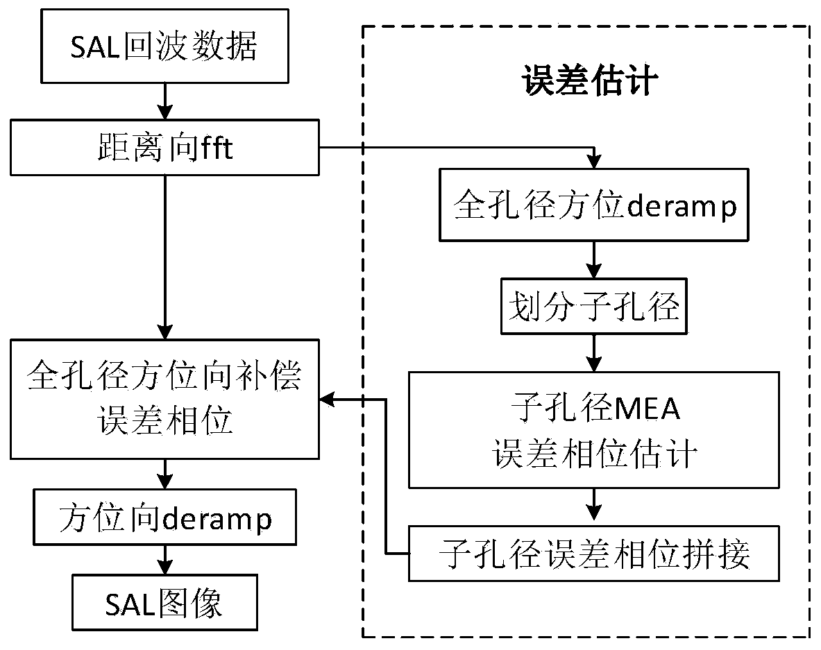
[0029] Since the synthetic aperture lidar is a synthetic aperture imaging technology working in the laser band, and because the working wavelength of the SAL is relatively short, for the airborne SAL, the vibration amplitude of the carrier aircraft is dozens of times of its wavelength, which will be introduced during the data acquisition process. For high-frequency or large-scale phase errors, it is difficult for traditional inertial navigation systems to achieve laser wavelength-level positioning accuracy. For this reason, the present invention has innovated and proposed a full-aperture self-focusing imaging algorithm. See figure 1 , including the following steps:

[0030] Step 1, generate the initial data matrix of synthetic aperture lidar imaging: for the measured SAL echo image, after data conversion, input the complex matrix of the converted SAL echo image, and generate the initial data matrix of SAL imaging, which is called a complete data block, It is waiting for the al...

Embodiment 2

[0040] The full-aperture imaging method based on the MEA algorithm is the same as in Embodiment 1, and the process of obtaining the SAL image echo data in step 2 includes:

[0041] A synthetic aperture lidar emits a chirp signal:

[0042]

[0043] Among them, rect( ) is a rectangular window function, For fast time, T p is the duration of the transmitted pulse, and γ is the modulation frequency.

[0044] The transmitted signal is reflected by the ground target point and then collected back to obtain the echo signal. Compared with the original transmitted signal, the echo signal has a certain delay. (R t is the instantaneous slant distance from the target to the aircraft, c is the electromagnetic wave propagation speed, which is equal to the speed of light), then the echo signal at this time is expressed as:

[0045]

[0046] where t m Indicates the azimuth slowing time, that is, the flight time of the carrier aircraft, t m It is reflected in the echo delay τ (if t...

Embodiment 3

[0048] The full-aperture imaging method based on the MEA algorithm is the same as that in Embodiment 1-2, and the compensation process of the focusing phase in the azimuth direction in step 3 includes:

[0049] 3a) Construct the matched filter function:

[0050] Range pulse pressure data at zero Doppler time t d The target echo for is:

[0051] the s r (t m )=exp(jπγ m (t m -t d ) 2 ) (3)

[0052] Among them, γ m is the azimuth modulation frequency;

[0053] The matched filter function is:

[0054]

[0055] 3b) Perform deramp, and the obtained signal is multiplied by the conjugate function of the target echo and the matched filter function:

[0056]

[0057] Among them, h * dr (t m ) means h dr (t m ) conjugate. The first exponential term of the above formula is a constant phase, which is related to the zero Doppler time t d proportional to the square of ; the second exponential term is γ m t d The complex sine wave (single frequency wave);

[0058] ...


PUM


Abstract

The invention discloses an SAL (synthetic aperture ladar) full-aperture imaging method based on MEA (minimum entropy autofocus) and deramp. With the method adopted, the problem of large movement errorbrought to echoes by the vibration of a carrying aircraft is solved. The method includes the following steps that: echo data signals are collected; range-direction pulse compression is performed on the received data; azimuth-direction deramp operation is performed on the range-direction pulse compressed data, so that the azimuth-direction focusing phase of the range-direction pulse compressed data can be compensated; a data block is divided into sub-apertures, phase error estimation is performed on sub-aperture data; sub-aperture phase errors are spliced, so that a full-aperture phase error is obtained; azimuth-direction phase error compensation is performed on the whole range-direction pulse compressed data; azimuth-direction derramp is carried out, the azimuth-direction pulse compression of the whole data of an SAL is achieved, the full-aperture imaging of the SAL is completed, and a high-resolution image is obtained. According to the method, sub-aperture division is performed on the data through a full-aperture imaging method; sub-aperture error phases are extracted through the MEA, all the error phases are spliced; overall phase compensation is performed on full-aperture data;and therefore, the utilization rate of original data is improved, estimated errors are more accurate, compensation is more effective, and the resolution of the imaging of the synthetic aperture laserradar is effectively improved. When the method is used for compensating high-order phase errors in the imaging of the synthetic aperture laser radar, a higher signal-to-noise ratio can be obtained, and the image resolution and image quality of the SAL can be improved.

Description

technical field [0001] The invention belongs to the technical field of radar data processing, and relates to a synthetic aperture lidar (SAL) phase compensation technology, in particular to a SAL full-aperture imaging method based on the combination of Minimum Entropy Autofocus (MEA) and deramp. For synthetic aperture lidar imaging. Background technique [0002] Synthetic Aperture Lidar (SAL) is a synthetic aperture imaging technology that works in the laser band, and its working wavelength is 10 times smaller than that of Synthetic Aperture Radar (SAR). 4-5 order of magnitude, according to the azimuth resolution formula ρ a =λ / (2Δθ) (λ represents the wavelength, Δθ represents the coherent integration angle), it can be seen that SAL can achieve better azimuth resolution in a shorter accumulation time than SAR, and its application prospects are very broad; while in SAL imaging , due to the short working wavelength of SAL, for airborne SAL, the vibration amplitude of the car...

Claims


Application Information

Patent Timeline
IPC IPC(8): G01S17/89
CPCG01S17/89
Inventor 郭亮许晴孙光才邢孟道胡以华
Owner XIDIAN UNIV
Learn More