VOC water removal collecting trap

A technology of traps and traps, which is applied in the field of environmental inspection and monitoring systems, can solve problems such as inconvenient installation and replacement, influence on monitoring results, and clean water inflow, so as to avoid and reduce material adsorption problems, The effect of increasing the heating rate

Pending Publication Date: 2019-08-06
北京鹏宇昌亚环保科技有限公司
View PDF0 Cites 4 Cited by
  • Summary
  • Abstract
  • Description
  • Claims
  • Application Information

AI Technical Summary

Problems solved by technology

The commonly used device is the electric refrigeration water removal trap, which has the following structural defects: first, the chromatographic column and the silanized water removal pipe surround the inside of the cylindrical refrigeration module, and the trapping and analysis are carried out inside the refrigeration module. And the water removal pipe surrounds the cold module. Once a problem occurs, it is inconvenient to install and replace, and even needs to be returned to the factory for repair. Secondly, the silanized water removal pipe is expensive and needs to be replaced regularly due to technical defects. The spiral structure is difficult when water enters the water removal pipe. Completely remove the incoming water. During the water removal process of the spiral structure, due to the spiral structure inside and the temperature difference between the inside and outside of the pipe, some water vapor will hang on the pipe wall, making it impossible to remove the water vapor. Affect the next test result; and the temperature measuring wire goes deep into the water removal glass tube. When the temperature measuring wire is replaced, the temperature measuring wire will bring the adsorbate into the water removal glass tube, resulting in inaccurate data and other problems; lastly, the outside of the refrigeration module Without a sealing cover, due to the temperature difference between the inside and outside of the refrigeration module, a large amount of ice forms at the joints around the refrigeration module, which affects the temperature control efficiency and thus affects the monitoring results
The above defects will reduce the accuracy of atmospheric monitoring data

Method used


Image

  • VOC water removal collecting trap
  • VOC water removal collecting trap
  • VOC water removal collecting trap

Examples


Embodiment Construction

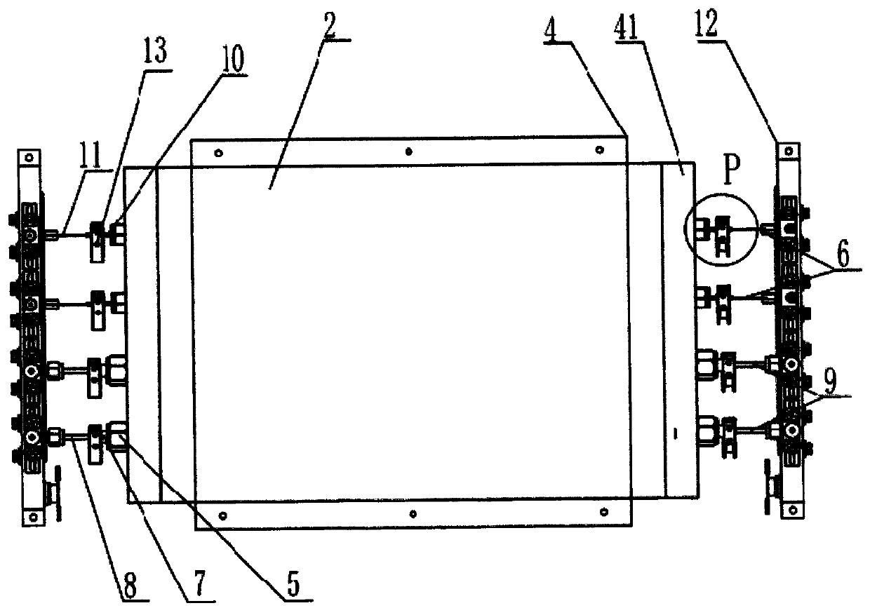
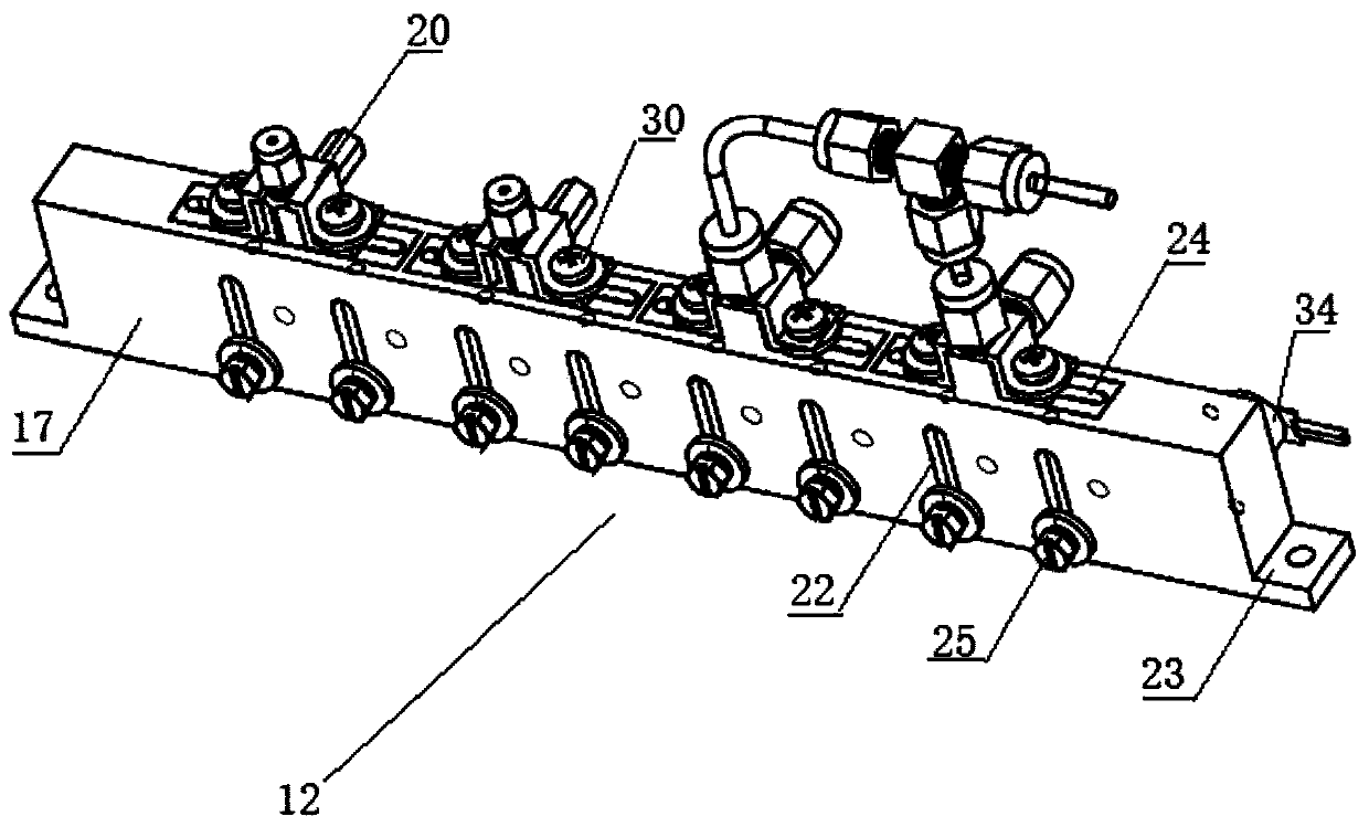
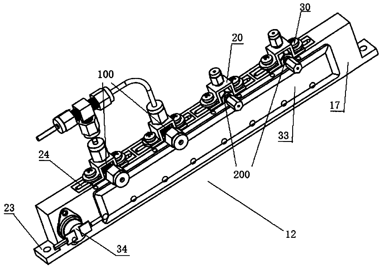
[0070] Most of the existing atmospheric VOC detection systems are structurally divided into three parts: refrigeration system, heating system, and control system. The commonly used device is the electric refrigeration water removal trap, which has the following structural defects: first, the chromatographic column and the silanized water removal pipe surround the inside of the cylindrical refrigeration module, and the trapping and analysis are carried out inside the refrigeration module. And the water removal pipe surrounds the cold module. Once a problem occurs, it is inconvenient to install and replace, and even needs to be returned to the factory for repair. Secondly, the silanized water removal pipe is expensive and needs to be replaced regularly due to technical defects. The spiral structure is difficult when water enters the water removal pipe. Thoroughly remove the incoming water; and the temperature measuring wire goes deep into the water removal pipe. When the temperat...


PUM


Abstract

A VOC water removal collecting trap of the invention relates to a processing system used for detecting an atmospheric sample. The invention aims at providing the water removal collecting trap with a simple structure and high detection precision. The VOC water removal collecting trap comprises a sealed cabin, a refrigeration cabin arranged in the sealed cabin, and heating components arranged in thesealed cabin and distributed on two sides of the refrigeration cabin. The sealed cabin is a cabin body formed by several aluminum plate materials. One side of the sealed cabin can be opened and closed. The refrigeration cabin comprises a refrigeration cabin body, connecting components installed on the two sides of the refrigeration cabin body, a water removal path and a trapping path which pass through the connecting components and the refrigeration cabin body. The connecting components are used for fixing the water removal path and the trapping path. The water removal path comprises a waterremoval pipe and a glass pipe. The glass pipe passes through the water removal pipe and is stretched out of the water removal pipe for a length. The trapping path comprises a trapping pipe and a chromatographic column. The chromatographic column passes through the trapping pipe and is stretched out of the trapping pipe for a length. The water removal pipe, the trapping pipe, and the glass pipe arestraight-through pipelines.

Description

technical field [0001] The invention relates to an environmental inspection and monitoring system, in particular to a system for monitoring atmospheric samples. Background technique [0002] For the existing atmospheric VOC monitoring system, its monitoring work process is generally divided into three main parts: sample pretreatment, pre-concentration and system cleaning. [0003] Pre-treatment process: Usually try to exclude factors that have an impact on VOC determination, such as water, carbon dioxide and other substances. [0004] Pre-concentration process: Pre-concentration is the enrichment process of the measurement target. The enrichment method adopted at this stage is mainly to freeze the measurement target in an ultra-low temperature environment to keep it in the collection tube, and then enter it through the carrier gas. The device performs detection, or the target is determined by adsorbing on the sorbent. [0005] System cleaning process: through the cleaning ...

Claims


Application Information

Patent Timeline
Patent Type & Authority Applications(China)
IPC IPC(8): G01N30/30G01N30/60G01N30/40G01N30/08
CPCG01N30/08G01N30/30G01N30/40G01N30/6047G01N2030/3092
Inventor 贾瑞平王澎蛟于腾跃罗潇廖益斌刘录华孔佩佩张春超崔金会
Owner 北京鹏宇昌亚环保科技有限公司
Why Eureka
Try Eureka