A wearable wheeled stop force feedback joint and force feedback control device
A control device and stop force technology, which is applied in the direction of program control manipulators, manufacturing tools, manipulators, etc., can solve the problems of unable to issue control commands in a timely and accurate manner, and the operator cannot sense the force of the execution end in time, so as to achieve good practicability and convenience, improve on-site immersion, and improve the effect of man-machine efficiency
- Summary
- Abstract
- Description
- Claims
- Application Information
AI Technical Summary
Problems solved by technology
Method used
Image
Examples
Embodiment 1
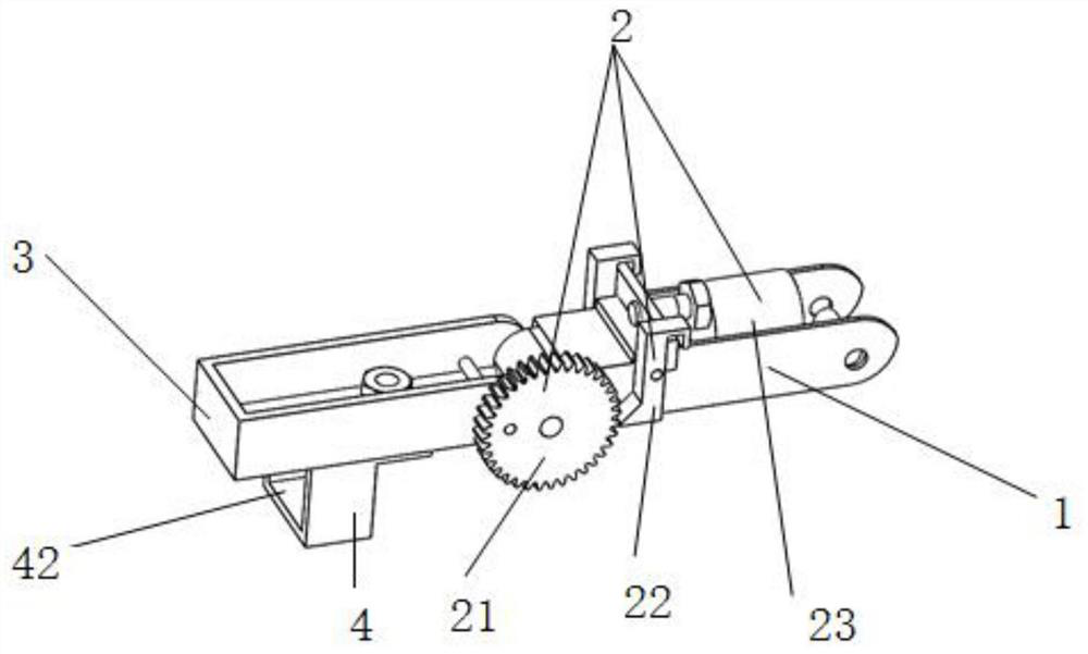
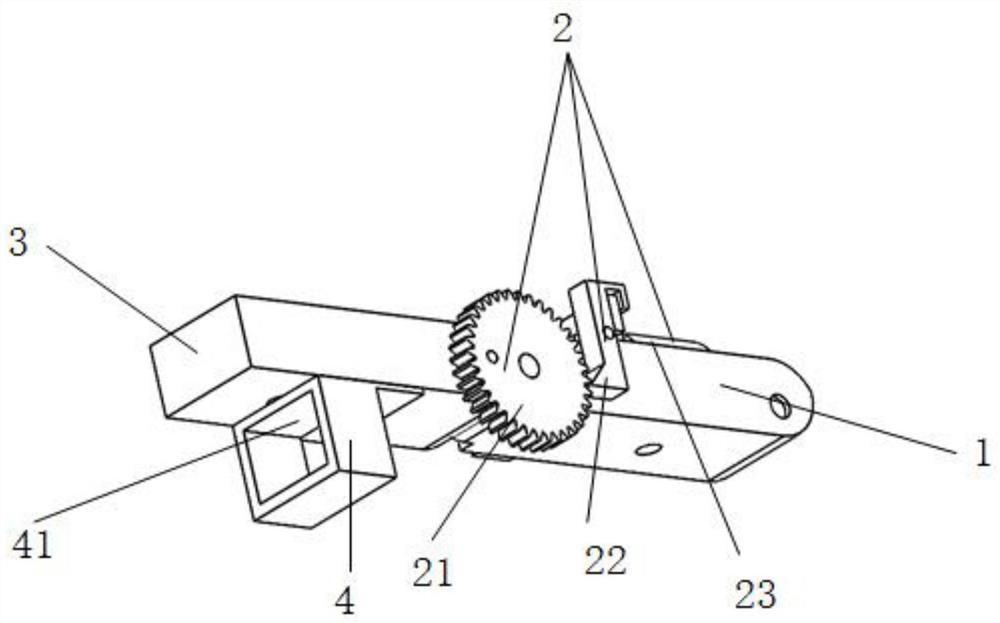
[0044] A specific embodiment of the present invention discloses a wearable wheel-type stop force feedback joint, comprising: a support base 1 , a follower rod 3 , a wheel-type stop mechanism 2 , a clasp 4 and fasteners. The wheel-type stop mechanism includes: a stop wheel 21 , a stop push rod 22 and a pusher 23 . The snap ring 4 is equipped with a follower rod A direction pressure sensor 41 and a follower rod B direction pressure sensor 42 .
[0045] Specifically, the follower lever 3 is hinged with the support base 1, and the stop wheel 21 of the wheel brake mechanism 2 is installed on the follower lever 3. When the follower lever 3 rotates relative to the support base 1 as the operator moves, The stop wheel 21 also rotates synchronously.
[0046] Preferably, the central axis of the stop wheel 21 coincides with the rotation center of the joint, that is, the central axis of the stop wheel is coaxial with the rotation center of the follower rod 3 and the support base 1, which ...
Embodiment 2
[0077] A wearable wheel-type stop force feedback control device, including at least one wheel-type stop force feedback joint, a motion capture system and a control device 13;
[0078] When there are multiple wheel-type stop force feedback joints, the plurality of wheel-type stop force feedback joints are combined into a wearable force feedback device through series or parallel connection;
[0079] The motion capture system is installed on the force feedback joint, including: the angle sensor installed at the joint rotation position and the pressure sensor installed on the joint, used to collect the motion information generated by the manipulation action, including: attitude, speed, acceleration and operating pressure;
[0080] The control device 13 is used to send the motion information collected by the motion capture system to the motion execution device for execution; the control device is also used to control the unlocking or locking of the stop wheel 21 of the wheel-type s...
Embodiment 3
[0092] This embodiment provides a wearable wheel-type stop force feedback control glove, and the wearable wheel-type stop force feedback control glove is used as a control end of the force feedback control system.
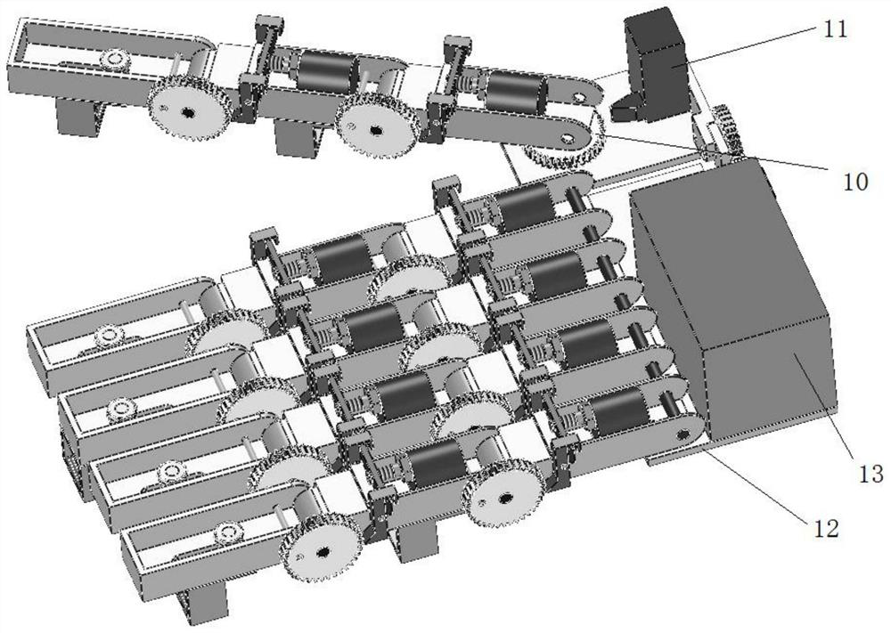
[0093] Specifically, such as image 3 As shown, the wearable wheeled stop force feedback control glove includes: mounting base 12, control device 13 and five force feedback finger joints.
[0094]Specifically, each force feedback finger joint is hinged in series with two wheel-type stop force feedback joints, that is, it includes three joints connected in series, has two rotation centers, and a wheel-type stopper is set at each rotation position. mechanism.
[0095] Each wheel-type brake force feedback joint includes two joint parts. After the two wheel-type brake force feedback joints are connected in series, the follower rod 3 of the previous wheel-type brake force feedback joint serves as the support for the latter wheel brake force feedback joint. Seat 1. Th...
PUM
 Abstract
Description
Claims
Application Information
 - R&D
- Intellectual Property
- Life Sciences
- Materials
- Tech Scout
- Unparalleled Data Quality
- Higher Quality Content
- 60% Fewer Hallucinations
Browse by: Latest US Patents, China's latest patents, Technical Efficacy Thesaurus, Application Domain, Technology Topic, Popular Technical Reports.
© 2025 PatSnap. All rights reserved.Legal|Privacy policy|Modern Slavery Act Transparency Statement|Sitemap|About US| Contact US: help@patsnap.com


