
A high thermal conductivity aluminum alloy polishing equipment

An aluminum alloy, high thermal conductivity technology, applied in grinding/polishing equipment, metal processing equipment, surface polishing machine tools, etc., can solve problems such as inconvenient movement, affecting polishing work efficiency, and high thermal conductivity aluminum alloy is large

Active Publication Date: 2021-07-06
江苏凯乐金属科技有限公司
View PDF0 Cites 1 Cited by
  • Summary
  • Abstract
  • Description
  • Claims
  • Application Information

AI Technical Summary

Problems solved by technology

With the rapid development of industrial economy, the demand for aluminum alloy welded structural parts is increasing, and the types of aluminum alloys are also increasing. High thermal conductivity aluminum alloy is a commonly used one. The processing of high thermal conductivity aluminum alloys often requires polishing to reduce the processed high The surface roughness of the thermally conductive aluminum alloy, the processing method to obtain a flat surface, during mechanical polishing, the high-speed rotating polishing wheel is pressed against the high thermally conductive aluminum alloy, so that the polishing wheel can roll and micro-cut the surface of the high thermally conductive aluminum alloy. At present, Some processed high thermal conductivity aluminum alloys cannot be completely fixed during processing, which affects the processing results, and some high thermal conductivity aluminum alloys are relatively large, which is inconvenient to move during processing, which greatly affects the efficiency of polishing. Therefore, it is necessary to design an aluminum alloy polishing equipment that fastens high thermal conductivity aluminum alloy, is stable, easy to operate, and can effectively improve processing efficiency.

Method used


Image

  • A high thermal conductivity aluminum alloy polishing equipment
  • A high thermal conductivity aluminum alloy polishing equipment

Examples


Embodiment Construction

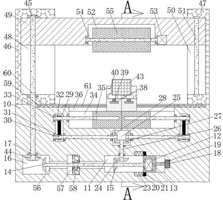
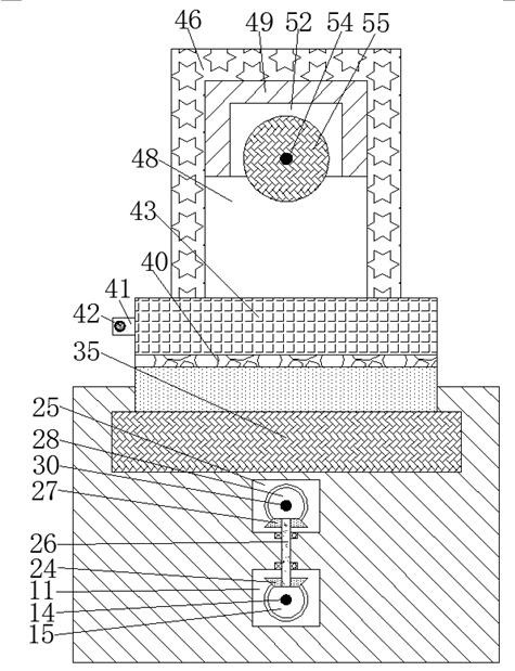
[0017] Combine below Figure 1-2 The present invention is described in detail, and for convenience of description, the orientations mentioned below are now stipulated as follows: figure 1 The up, down, left, right, front and back directions of the projection relationship itself are the same.

[0018] refer to Figure 1-2 , a high thermal conductivity aluminum alloy polishing equipment of the present invention, comprising a workbench 10 and a power chamber 11 arranged in the workbench 10, a slider 12 is slidably connected to the power chamber 11, and the slider 12 The upper is connected with a limit device, and a mobile motor 13 is fixed inside the slider 12, and a transmission shaft 14 extending to the left is fixed on the output shaft of the mobile motor 13, and a first transmission shaft 14 is fixed on the transmission shaft 14. Steering bevel gear 15, the upper end of the first steering bevel gear 15 is meshed and connected with a clamping device, the clamping device is f...


PUM


Abstract

The invention discloses a high thermal conductivity aluminum alloy polishing equipment, which comprises a workbench and a power chamber arranged in the workbench, a sliding block is slidably connected to the power chamber, and a limiting device is connected to the slider. A mobile motor is fixed inside the slider, and a transmission shaft extending to the left is fixed on the output shaft of the mobile motor. The first steering bevel gear is fixed on the transmission shaft, and the first steering bevel gear is fixed on the transmission shaft. The upper end is meshed and connected with a clamping device, the clamping device is fixed with a fixing mechanism, the left end wall of the power chamber is provided with a gear connection cavity, and the left end of the transmission shaft is fixed with a second steering bevel gear, The automatic polishing equipment of the present invention is more reasonable and ingenious in overall structure, easy to operate, and has high efficiency in processing aluminum alloys with high thermal conductivity. A single driving motor can realize the function of the clamping and fixing mechanism of the lifting polishing device, and the use safety is high. It has high use and promotion value.

Description

technical field [0001] The invention relates to the field of high thermal conductivity aluminum alloy processing, in particular to a high thermal conductivity aluminum alloy polishing equipment. Background technique [0002] Aluminum alloy is the most widely used non-ferrous metal structural material in industry, and has been widely used in aviation, aerospace, automobile, machinery manufacturing, shipbuilding and chemical industry. With the rapid development of industrial economy, the demand for aluminum alloy welded structural parts is increasing, and the types of aluminum alloys are also increasing. High thermal conductivity aluminum alloy is a commonly used one. The processing of high thermal conductivity aluminum alloys often requires polishing to reduce the processed high The surface roughness of the thermally conductive aluminum alloy, the processing method to obtain a flat surface, during mechanical polishing, the high-speed rotating polishing wheel is pressed agains...

Claims


Application Information

Patent Timeline
Patent Type & Authority Patents(China)
IPC IPC(8): B24B29/02B24B41/06B24B55/06B24B47/12B24B27/00B24B27/02B24B41/02B24B55/00
CPCB24B27/00B24B27/02B24B29/02B24B41/02B24B41/06B24B47/12B24B55/00B24B55/06
Inventor 郝秀兰叶利红
Owner 江苏凯乐金属科技有限公司
Learn More