
High-integration-level optical protection switch

A high-integration, optical protection technology, applied in the field of optical communications, can solve the problems of long production cycle, large packaging volume, and high insertion loss of optical protection switches, and achieve the effect of overcoming long production cycle, small packaging volume, and low insertion loss

Inactive Publication Date: 2019-08-02
GUANGXUN SCI & TECH WUHAN
View PDF9 Cites 0 Cited by
  • Summary
  • Abstract
  • Description
  • Claims
  • Application Information

AI Technical Summary

Problems solved by technology

[0003] The embodiment of the present application provides a highly integrated optical protection switch, which solves the problems of long production cycle, high insertion loss, and large packaging volume of the optical protection switch in the prior art.

Method used


Image

  • High-integration-level optical protection switch
  • High-integration-level optical protection switch
  • High-integration-level optical protection switch

Examples


Embodiment 1

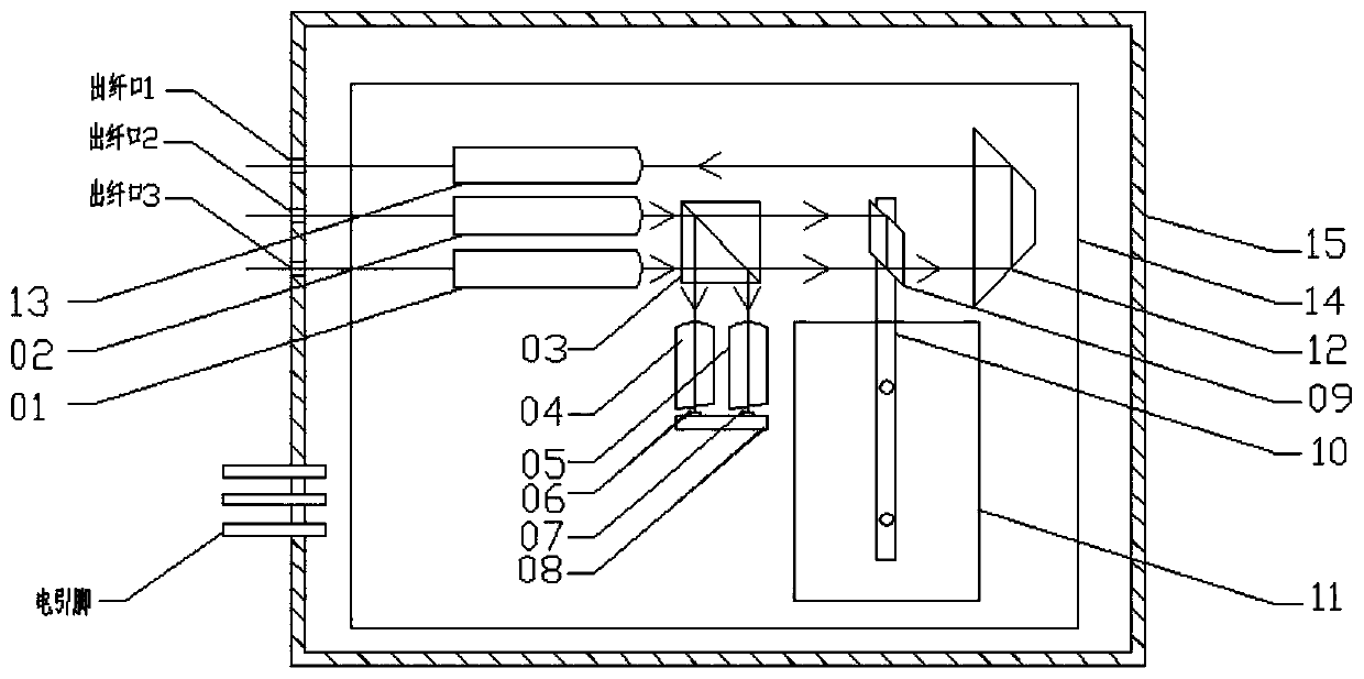
[0043] A highly integrated optical protection switch, such as figure 2 As shown, it includes: main path incident fiber collimator 01, backup path incident fiber collimator 02, beam splitter 03, first converging lens 04, second converging lens 05, main path port optical detection chip 06, backup path Port light detection chip 07, ceramic pad 08, orthorhombic prism 09, connecting rod 10, relay 11, steering prism 12, fiber optic collimator 13 at the exit end, inner bracket 14, and outer shell 15.

[0044] The main incident fiber collimator 01 and the secondary incident fiber collimator 02 are passive devices that collimate the beam with a large divergence angle emitted from the optical fiber into parallel light, and are used for the input of optical signals.

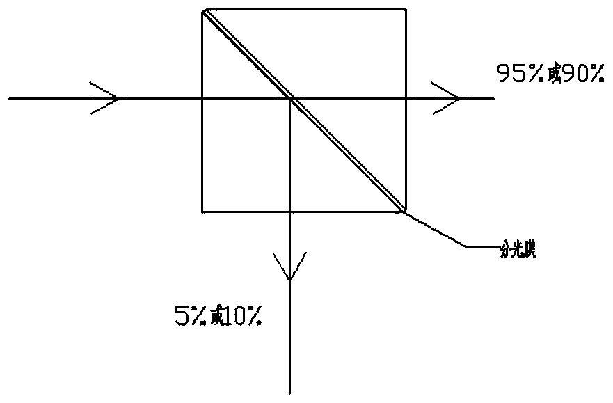
[0045]The beam splitter 03 is a beam splitter with a 45° incidence, which is used to split the 45° incident light into two beams, one of which is reflected and the other is transmitted, and the light intensity ratio of the...

Embodiment 2

[0060] Compared with embodiment 1, the highly integrated optical protection switch provided by embodiment 2 does not include the turning prism 12, as Figure 9 As shown, the device achieves fiber output on both sides of the outer shell 15, which can effectively reduce the width of the device. Other structures and specific implementation methods are the same as those in Embodiment 1, and will not be repeated here.

[0061] In summary, a highly integrated optical protection switch proposed by the present invention adopts a free-space optical path, integrates two functions of optical splitting detection (TAP PD) and 1x2 optical switch, overcomes the shortcomings of traditional technologies, and has the advantages of short production cycle, insertion With the advantages of low loss and small size, it has great application prospects and market value.


PUM


Abstract

The invention belongs to the technical field of optical communication, and discloses a high-integration-level optical protection switch which comprises a main path detection unit, a standby path detection unit, a beam splitter, an optical switch switching unit and an emergent end optical fiber collimator. The main path detection unit comprises a main path incident optical fiber collimator, a firstconvergent lens and a main path port optical detection chip; the standby path detection unit comprises a standby path incident optical fiber collimator, a second convergent lens and a standby path port optical detection chip. The invention solves the problems of long manufacturing period, high insertion loss and large packaging size of the optical protection switch in the prior art, and has the advantages of short manufacturing period, low insertion loss, small packaging size and the like.

Description

technical field [0001] The invention relates to the technical field of optical communication, in particular to a highly integrated optical protection switch. Background technique [0002] The 1x2 optical switch is widely used in the optical line protection (Optical Line Protect) system. In specific applications, a light splitting detector (TAP PD) is generally configured on each port of the 1x2 optical switch device to monitor the main line and the backup line. Perform optical power detection to realize the system to perform active-standby automatic switching according to the real-time optical power level of the line. At present, it is realized in the process by combining discrete devices through processes such as welding and fiber coiling to make optical protection functional modules, such as figure 1 As shown, but this solution has disadvantages such as long production cycle, high insertion loss, and large package volume. Contents of the invention [0003] The embodime...

Claims


Application Information

Patent Timeline
IPC IPC(8): G02B6/35
CPCG02B6/352G02B6/3586G02B6/3594
Inventor 刘宁肖清明王敏
Owner GUANGXUN SCI & TECH WUHAN
Learn More