A four-track bed

A technology of rail bed and inclined bed, applied in the field of four-rail bed, can solve the problems of affecting the accuracy of processing, difficult to clean, shorten the service life of guide rails, etc., and achieve the effects of improving rigidity, convenient operation and reducing floor space

Active Publication Date: 2020-03-31
CHONGQING HONGGANG CNC MACHINE TOOL
View PDF2 Cites 0 Cited by
  • Summary
  • Abstract
  • Description
  • Claims
  • Application Information

AI Technical Summary

Problems solved by technology

combine figure 2 As shown, whether it is the saddle guide rail 3 or the tailstock guide rail 5, the top surface of the guide rail has a certain inclination, that is to say, there is an angle between the top surface of the guide rail and the top surface of the base 1. Since the top surface of the guide rail is inclined Therefore, the slider at the bottom of the saddle assembly 8 slidably connected to the saddle guide rail 3 and the slider of the tailstock assembly 4 slidably connected to the tailstock guide rail 5 need to be designed to cooperate with the top surface of the guide rail. In this way, the production and processing of the slider is relatively harsh, and the production cost of the slider is relatively high, and it is troublesome to install the slider on the guide rail with an inclined top surface.
Moreover, the gravity on the saddle guide rail 3 and the tailstock guide rail 5 is also relatively large. Since the top surface of the guide rail is inclined, the force on the top of the guide rail is uneven, and the top surface of the guide rail is easily deformed, thereby making the service life of the guide rail longer. Shorter, affecting the accuracy of processing
[0005] In the same way, the pair of tailstock guide rails 5 on the bed of the machine tool are usually provided with high and low steps at present, that is, the height of the guide rail on the left side of the tailstock guide rail 5 is less than the height of the guide rail on the right side of the tailstock guide rail 5, and there is a gap between the two. There is an included angle between the formed plane and the top surface of the base 1, so that the gravity of the tailstock assembly 4 borne by the tailstock guide rail 5 is unstable, and the tailstock guide rail 5 is easily deformed, so that the service life of the tailstock guide rail 5 is shortened. Short, it will also affect the accuracy of processing
[0006] In addition, the metal iron filings produced by current processing are easy to accumulate at the root of the tailstock guide rail 5, and it is difficult to clean it. In addition, the accumulated iron filings are also easy to enter between the slide block of the tailstock assembly 4 and the tailstock guide rail 5. Occasionally affect the normal sliding of the tailstock assembly 4, affecting the machining accuracy

Method used


Image

  • A four-track bed
  • A four-track bed
  • A four-track bed

Examples


Embodiment 1

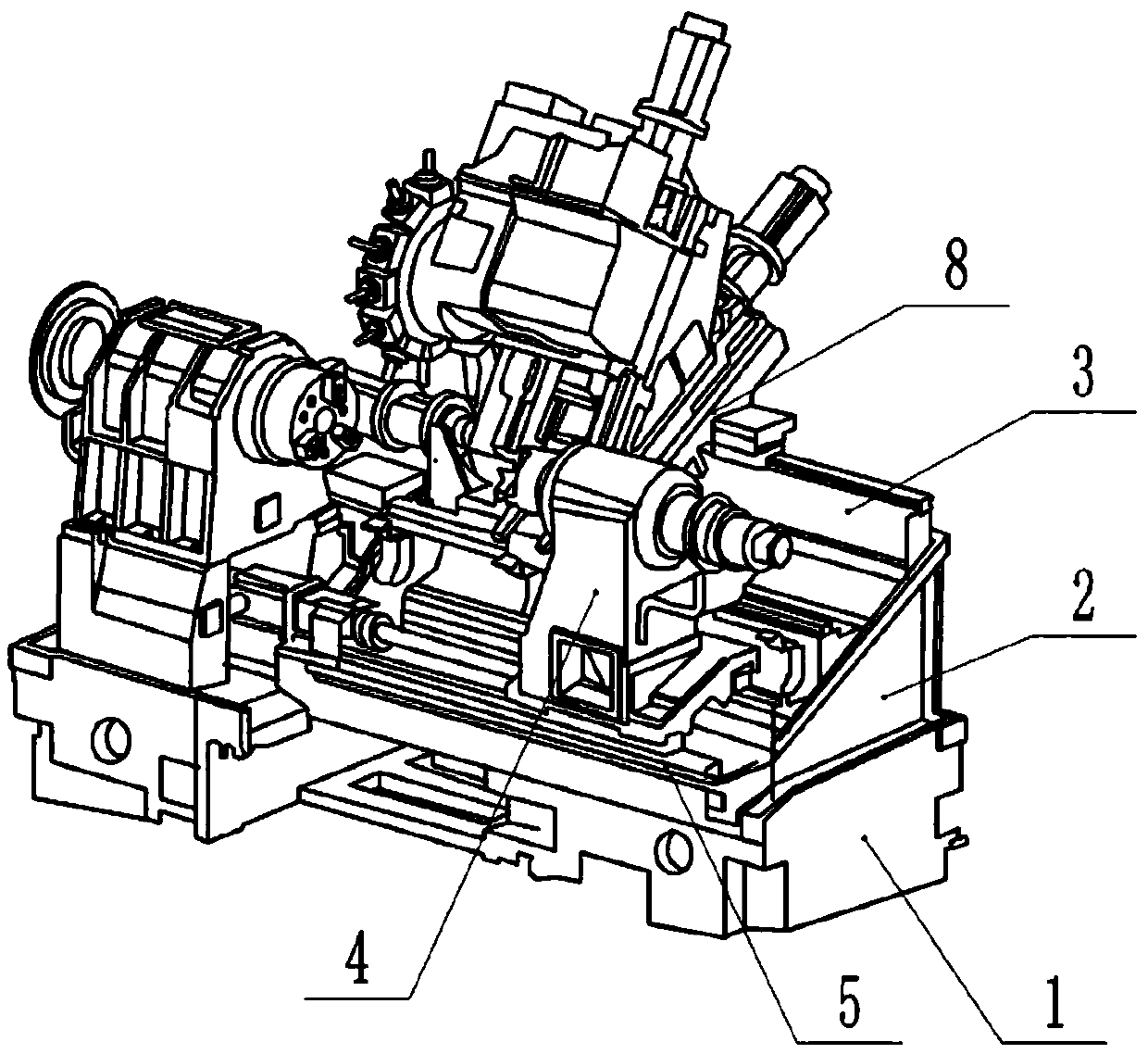
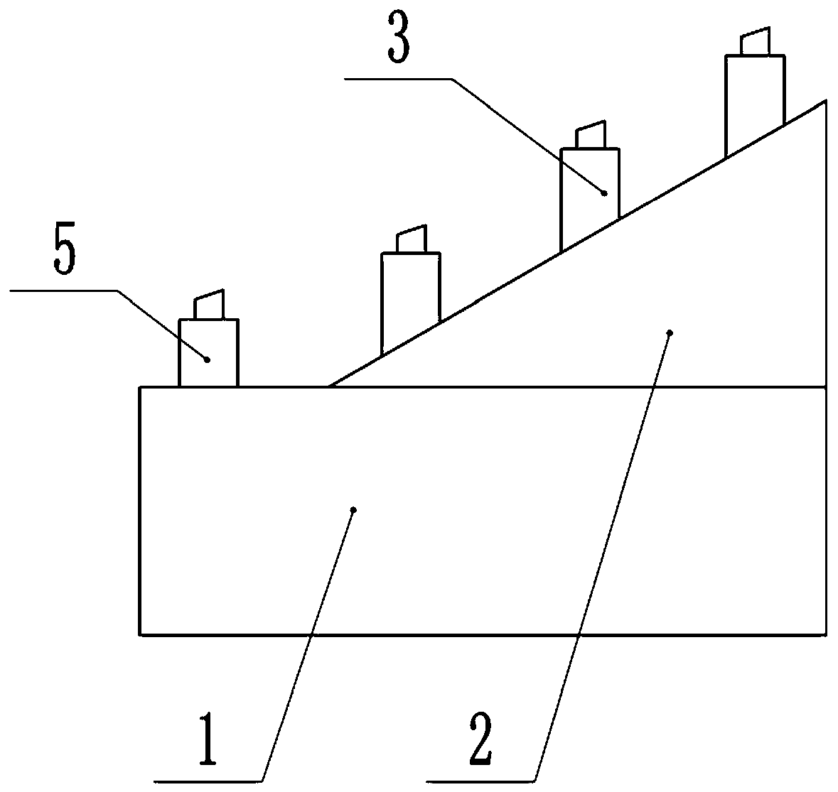
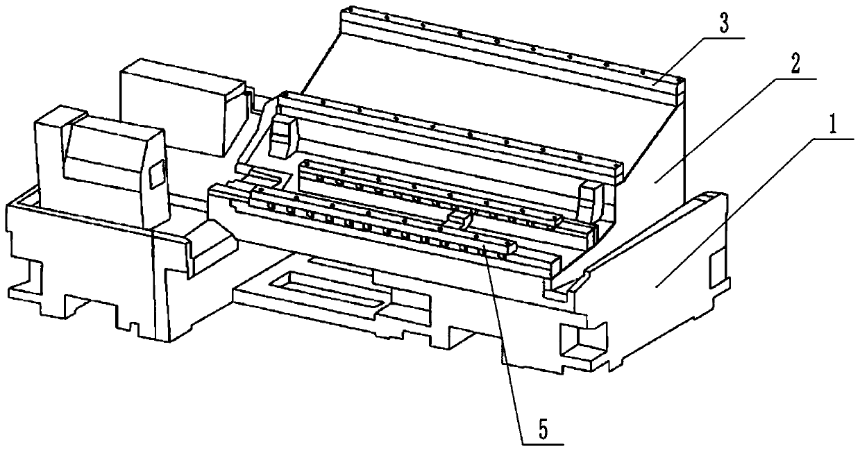
[0032] Basic as attached image 3 Shown: a four-rail bed, including a base 1, an inclined bed 2, a tailstock guide 5 and a saddle guide 3, the inclined bed 2 is fixed on the base 1 by screws, and the saddle guide 3 is fixed on the inclined bed 2, the tailstock guide rail 5 is fixed on the top surface of the base 1, and the top surface of the base 1 is a plane and parallel to the horizontal plane. The top surface of the tailstock guide rail 5 and the top surface of the saddle guide rail 3 are all parallel to the top surface of the base 1; They are all on the same plane and parallel to the top surface of the base 1 . Saddle rail 3 for use in figure 1 The middle saddle assembly 8 slides, and the tailstock guide rail 5 is used to make the tailstock assembly 4 slide.

[0033] A cleaning assembly for cleaning the tailstock guide rail 5 is provided on the base 1 . In this embodiment, the cleaning assembly includes an air blowing pump and an air blowing pipe, the air blowing pipe ...

Embodiment 2

[0038] combine Figure 4 As shown, the cleaning assembly in this embodiment includes two sides of tailstock guide rail 5 Figure 4 The rotating disk 10 in the middle, the rotating disk 10 rolls on the base 1 along the length direction of the tailstock guide rail 5, and a rotating shaft 23 is connected between the two rotating disks 10, and the two ends of the rotating shaft 23 pass through the rotating disk 10 and are welded on the On the inner wall of the rotating disk 10 away from the tailstock guide rail 5, the middle part of the rotating shaft 23 is connected with a bearing 19 for rotation. Specifically, the bearing 19 is sleeved in the middle part of the rotating shaft 23, and the inner ring of the bearing 19 is welded to the rotating shaft 23; of course, it can not be used here. The bearing 19 may be rotatably connected with the rotating shaft 23 through a sleeve. combine Figure 5 As shown, the cleaning assembly also includes a driving block 20, the driving block 20 i...

Embodiment 3

[0044] In this embodiment, the rotating disk 10 is provided with several openings on the side away from the tailstock guide rail 5, and a cover is provided on the openings. When the iron filings in the cavity are almost collected, the cover can be taken out, the opening is opened, and the iron Chips are automatically discharged from the opening, thereby realizing the discharge of iron filings. Of course, the cavity is detachably connected with a magnet bar. If there is a groove on the inner wall of the cavity, insert the magnet bar in the groove, and the magnet bar can collect the iron filings in the cavity. When the iron filings are full, , open the cover, and take out the magnet bar from the opening, so as to realize taking out the iron filings from the cavity.


PUM


Abstract

The invention relates to the field of numerical control machine tools, in particular to a four-rail lathe bed. The four-rail lathe bed comprises a base, an inclined lathe bed, tailstock guide rails and a saddle guide rail, wherein the inclined lathe bed is located on the base, the saddle guide rail is located on the inclined lathe bed, the tailstock guide rails are located on the base, and the topsurfaces of the tailstock guide rails and the top surface of the saddle guide rail are parallel to the horizontal plane; the tops of the plurality of tailstock guide rails are located on the same horizontal plane; and a cleaning assembly used for cleaning the tailstock guide rails is arranged on the base. According to the scheme, the machining precision of the whole machine tool is improved.

Description

technical field [0001] The invention relates to the field of numerically controlled machine tools, in particular to a four-rail bed. Background technique [0002] The basic component of the CNC lathe is the bed, and one of the important bed layout designs is the inclined bed. [0003] The CNC machine tool adopts the inclined bed layout, which can not only reduce the floor area of ​​the machine tool under the same conditions; but also improve the rigidity of the bed through the overall closed section design, especially when processing workpieces, due to the inclined bed Inclined setting, different angles of tools can be arranged on the inclined bed, so that the workpiece can be processed from multiple angles and in all directions, and the operation is more convenient. Therefore, CNC machine tools with inclined bed layout have been widely used in the lathe machining industry in recent years for the multi-variety processing of sophisticated and complex rotary parts. [0004] ...

Claims


Application Information

Patent Timeline
Patent Type & Authority Patents(China)
IPC IPC(8): B23Q1/01B23Q11/00
CPCB23Q1/015B23Q1/017B23Q11/0046
Inventor 汪传宏
Owner CHONGQING HONGGANG CNC MACHINE TOOL
Why Eureka
Try Eureka